| C H A P T E R 1 |
|
Initial Inspection of the Server |
This chapter includes the following topics:
|
Note - The information in this chapter applies to the original Sun Fire X4600 server, and to the Sun Fire X4600 M2 server, unless otherwise noted in the text. |
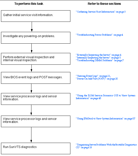
Use the following flowchart as a guideline for using the subjects in this book to troubleshoot the server.

The first step in determining the cause of the problem with the server is to gather whatever information you can from the service-call paperwork or the onsite personnel. Use the following general guideline steps when you begin troubleshooting.
To gather service visit information:
1. Collect information about the following items:
2. Document the server settings before you make any changes.
If possible, make one change at a time, in order to isolate potential problems. In this way, you can maintain a controlled environment and reduce the scope of troubleshooting.
3. Take note of the results of any change you make. Include any errors or informational messages.
4. Check for potential device conflicts before you add a new device.
5. Check for version dependencies, especially with third-party software.
Improperly set controls and loose or improperly connected cables are common causes of problems with hardware components.
1. Check that AC power cords are attached firmly to the server's power supplies and to the AC sources.
2. Check that the main cover is firmly in place.
There is an intrusion switch on the motherboard that automatically shuts down the server power to standby mode when the cover is removed.
To perform a visual inspection of the external system:
1. Inspect the external status indicator LEDs, which can indicate component malfunction.
For the LED locations and descriptions of their behavior, see External Status Indicator LEDs.
2. Verify that nothing in the server environment is blocking air flow or making a contact that could short out power.
3. If the problem is not evident, continue with the next section, Internally Inspecting the Server.
To perform a visual inspection of the internal system:
1. Choose a method for shutting down the server from main power mode to standby power mode.
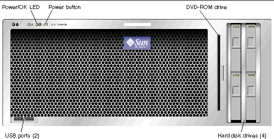
When main power is off, the Power/OK LED on the front panel will begin flashing, indicating that the server is in standby power mode.

2. Remove the server cover, as required.
For instructions on removing the server cover, refer to the Sun Fire X4600 and Sun Fire X4600 M2 Servers Service Manual, 819-4342.
3. Inspect the internal status indicator LEDs, which can indicate component malfunction.
For the LED locations and descriptions of their behavior, see Internal Status Indicator LEDs.
|
Note - The server must be in standby power mode for viewing the internal LEDs. |
4. Verify that there are no loose or improperly seated components.
5. Verify that all cable connectors inside the system are firmly and correctly attached to their appropriate connectors.
6. Verify that any after-factory components are qualified and supported.
For a list of supported PCI cards and DIMMs, refer to the Sun Fire X4600 and Sun Fire X4600 M2 Servers Service Manual, 819-4342.
7. Check that the installed DIMMs comply with the supported DIMM population rules and configurations, as described in Troubleshooting DIMM Problems.
9. To restore main power mode to the server (all components powered on), use a ballpoint pen or other stylus to press and release the Power button on the server front panel. See FIGURE 1-2.
When main power is applied to the full server, the Power/OK LED next to the Power button lights and remains lit.
10. If the problem with the server is not evident, you can try viewing the power-on self test (POST) messages and BIOS event logs during system startup. Continue with Viewing Event Logs.
Use this section to troubleshoot problems with memory modules, or DIMMs.
|
Note - For information on Sun's DIMM replacement policy for x64 servers, contact your Sun Service representative. |
This section describes system behavior for the two types of DIMM errors: uncorrectable errors (UCEs) and correctable errors (CEs), and also describes BIOS DIMM error messages.
For all operating systems (OS's), the behavior is the same for UCEs:
1. When an UCE occurs, the memory controller causes an immediate reboot of the system.
2. During reboot, the BIOS checks the NorthBridge memory controller's Machine Check registers and determines that the previous reboot was due to an UCE, then reports this in POST after the memtest stage:
A Hypertransport Sync Flood occurred on last boot
3. Memory reports this event in the service processor's system event log (SEL) as shown in the sample IPMItool output below:
# ipmitool -H 10.6.77.249 -U root -P changeme -I lanplus sel list
f000 | 02/16/2006 | 03:32:38 | OEM #0x12 |
f100 | OEM record e0 | 00000000040f0c0200200000a2
f200 | OEM record e0 | 01000000040000000000000000
f300 | 02/16/2006 | 03:32:50 | Memory | Uncorrectable ECC | CPU 1 DIMM 0
f400 | 02/16/2006 | 03:32:50 | Memory | Memory Device Disabled | CPU 1 DIMM 0
f500 | 02/16/2006 | 03:32:55 | System Firmware Progress | Motherboard initialization
f600 | 02/16/2006 | 03:32:55 | System Firmware Progress | Video initialization
f700 | 02/16/2006 | 03:33:01 | System Firmware Progress | USB resource configuration
At this time, CEs are not logged in the server's system event logs. They are reported or handled in the supported OS's as follows:
1. A Machine Check error-message bubble pops up on task bar.
2. The user must manually go into Event Viewer to view errors. Access Event Viewer through this menu path:
Start-->Administration Tools-->Event Viewer
3. The user can then view individual errors (by time) to see details of the error.
There is no reporting of CEs in Solaris x86 at this time.
There is no reporting of CEs in the Linux distributions that Sun supports on this server at this time.
The BIOS will display and log three types of DIMM error messages:
The following conditions will cause this error message:
The following condition will cause this error message:
The following conditions will cause this error message:
Only Samsung, Micron, Infineon, and SMART DIMMs are supported.
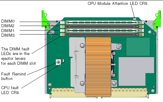
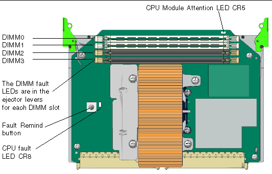
In the Sun Fire X4600/X4600 M2 servers, four DIMM slots are on each removable CPU module. The DIMM fault LEDs in the DIMM slot ejector levers indicate which DIMM pair has failed. These DIMM fault LEDs can be lit for up to one minute by a capacitor on the CPU module, even after the CPU module is removed from the server. To light the fault LED from the capacitor, push the small button on the CPU module labelled "FAULT REMIND BUTTON."
|
Note - The Sun Fire X4600 and the Sun Fire X4600 M2 Servers have slightly different CPU modules. The visible difference is that the Sun Fire X4600 CPU modules have DIMM slots in alternating white and black, while the Sun Fire X4600 M2 has two white DIMM slots adjacent to each other, and two black slots adjacent to each other. See FIGURE 1-3 and FIGURE 1-4 for the locations of the DIMMs and of the fault LEDs on the CPU module. |
The DIMM ejector levers contain LEDs that can indicate a faulty DIMM.
The system designation of the DIMM slots on each Sun Fire X4600 CPU module is shown in FIGURE 1-3.

The system designation of the DIMM slots on each Sun Fire X4600 CPU module is shown in FIGURE 1-3.

The system designation of the DIMM slots on each Sun Fire X4600 M2 CPU module is shown in FIGURE 1-4.
|
Note - The original Sun Fire X4600 servers use only DDR1 DIMMs. The Sun Fire X4600 M2 servers use only DDR2 DIMMs. |
If your log files report an ECC error or a problem with a DIMM, complete the steps below until you can isolate the fault.
In this example, the log file reports an error with the DIMM in CPU0, slot 1. The fault LEDs on CPU0, slots 1 and 0 are lit.
To isolate and correct DIMM ECC errors:
1. If you have not already done so, shut down your server to standby power mode and remove the cover.
Refer to the Sun Fire X4600 and Sun Fire X4600 M2 Servers Service Manual, 819-4342.
2. Inspect the installed DIMMs to ensure that they comply with the DIMM Population Rules.
3. Inspect the fault LEDs on the DIMM slot ejectors and the CPU fault LED on the CPU module. See FIGURE 1-3.
If any of these LEDs are lit, they can indicate the component with the fault.
4. Disconnect the AC power cords from the server.
5. Remove the CPU module that has the DIMM problem.
Refer to the Sun Fire X4600 and Sun Fire X4600 M2 Servers Service Manual, 819-4342.
6. Remove the DIMMs from the CPU module.
Refer to the Sun Fire X4600 and Sun Fire X4600 M2 Servers Service Manual, 819-4342.
7. Visually inspect the DIMMs for physical damage, dust, or any other contamination on the connector or circuits.
8. Visually inspect the DIMM slot for physical damage. Look for cracked or broken plastic on the slot.
9. Dust off the DIMMs, clean the contacts, and reseat them.
10. If there is no obvious damage, exchange the individual DIMMs between the two slots of a given pair. Ensure that they are inserted correctly with ejector latches secured. Using the slot numbers from the example:
a. Remove the DIMMs from CPU0, slots 1 and 0.
b. Reinstall the DIMM from slot 1 into slot 0.
c. Reinstall the DIMM from slot 0 into slot 1.
11. Reinstall the CPU module that has the DIMM problem.
Refer to the Sun Fire X4600 and Sun Fire X4600 M2 Servers Service Manual, 819-4342.
12. Reconnect AC power cords to the server.
13. Power on the server and run the diagnostics test again.
15. Shut down the server again and disconnect the AC power cords.
16. Remove the CPU module that has the DIMM problem, and remove another CPU module that does not indicate a DIMM problem.
Refer to the Sun Fire X4600 and Sun Fire X4600 M2 Servers Service Manual, 819-4342.
17. Remove both DIMMs of the pair and install them into paired slots on the second CPU module that did not indicate a DIMM problem.
Using the slot numbers in the example, install the two DIMMs from CPU0, slots 1 and 0 into CPU1, slots 1 and 0 or CPU1, slots 3 and 2.
18. Reinstall both CPU modules that you removed.
Refer to the Sun Fire X4600 and Sun Fire X4600 M2 Servers Service Manual, 819-4342.
19. Reconnect AC power cords to the server.
20. Power on the server and run the diagnostics test again.
Copyright © 2006, Sun Microsystems, Inc. All Rights Reserved.