| Sun Ultra 20 M2 Workstation Installation Guide |
| Sun Ultra 20 M2 Workstation Installation Guide |
| C H A P T E R 1 |
| 1 |
|
Introduction to the Sun Ultra 20 M2 Workstation Hardware |
This chapter provides an overview of the Sun Ultra 20 M2 Workstation hardware.
This chapter includes the following sections:
Read the following documents for safety information:
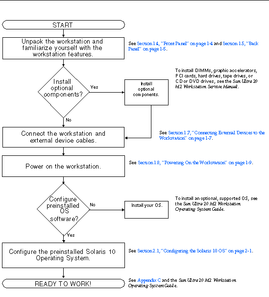
Use the following flowchart as a process tool to assist you with installation of the Sun Ultra 20 M2 Workstation.
Flowchart showing the installation process that is documented in this guide.
Carefully unpack all workstation components from the packing cartons. The following items are contained in the package.
If you ordered an optional country kit, the kit ships in a separate package and includes a power cable, keyboard, and mouse.
|
Note - Use only a Type 7 keyboard and Type 7 mouse with the Sun Ultra 20 M2 Workstation. |
FIGURE 1-2 illustrates the front panel of the Sun Ultra 20 M2 Workstation. TABLE 1-2 lists the components called out in the figure.

FIGURE 1-3 depicts the back panel of the Sun Ultra 20 M2 Workstation. TABLE 1-3 lists the components called out in the figure.

|
Onboard DB15 VGA graphics connector (for ES 1000 graphics controller) |
|||
FIGURE 1-4 illustrates some of the interior components of the Sun Ultra 20 M2 Workstation. TABLE 1-4 lists the items called out in the figure.
For further information about PCI slots, see PCI-E and PCI Expansion Slots. For component installation, removal, and replacement procedures, see the Sun Ultra 20 M2 Workstation Service Manual.

|
PCI Express slots (3) numbered PCI-E slot 0 (top) to PCI-E slot 2 |
|||
FIGURE 1-5 illustrates the external device cable connections to the workstation.

Perform this procedure to connect external devices to the workstation.
1. Connect the workstation power cord to a grounded electrical outlet.
2. Connect the keyboard to a USB connector on the back or front panel.
3. Connect the mouse to the USB connector on the underside of the keyboard or to a USB connector on the front or back panel.
4. Connect the Ethernet cable to either Ethernet connector on the Sun Ultra 20 M2 Workstation, and connect the other end of the cable to an Ethernet RJ-45 jack.
5. Connect the monitor cable as follows:
Your graphics card might require a DVI cable to connect to your monitor.

6. Connect any additional external devices to the workstation's other connectors.
Perform this procedure to power on the workstation.
1. Turn on the power to the monitor and to all external devices.
2. Turn the power switch on the rear of the workstation to the On ( | ) position.
3. Press and release the power switch on the front panel.
4. After several seconds, verify that the platform power LED next to the power switch is lit.
The platform power LED lights after the workstation begins the internal booting process.
5. If you need to change the system parameters in the BIOS, press the F2 key during the POST process to access the BIOS Setup Utility.

|
Caution - Be careful when making changes to the system BIOS, as some changes can cause your system to malfunction. |
1. Save your data and close any open applications.
2. Read both of the following power-off options, and then follow one of the options to turn off the workstation.
In most cases, this initiates an orderly shutdown of the operating system and shuts off the workstation power.

|
Caution - To avoid data loss, use the first option whenever possible. |
This option shuts down the power to the workstation but does not initiate an orderly shutdown of the operating system. This option might result in data loss.
If the proceeding options do not power off the workstation, turn the power switch on the back panel to the Off ( 0 ) position.
After powering off the workstation, wait at least four seconds before powering on the workstation again.
The boot menu lists the devices from which the system can boot. If you want to boot from a newly installed or attached device, you must add it to the boot menu.
To add or remove devices to/from the boot menu (accessed by pressing the F8 key during boot), perform the following steps:
1. Press the F2 key during system boot.
The BIOS Setup screen displays.
2. In the Boot Settings menu, add or remove the device from the boot device list.
3. Press the F10 key to save your settings and exit.
| Sun Ultra 20 M2 Workstation Installation Guide | 819-6587-12 |
Copyright © 2007, Sun Microsystems, Inc. All Rights Reserved.