Replacing the Motherboard
The following sections describe how to remove and install the Sun Ultra 27 workstation system motherboard.
Note –
The motherboard is not a CRU and should be replaced only by trained field service technicians.
 To Remove the Motherboard
-
Power off the workstation using the procedure described in the section, To Power Off the Workstation.
-
Remove the left-side access panel using the procedure described in the section, To Remove the Left-Side Access Panel.
-
Gently lay the system on its right side on a stable, nonslip surface.
-
Remove the fan assembly using the procedure described in the section, Replacing the System Fan.
-
Remove any PCIe cards installed on the motherboard (see Removing and Installing PCIe Cards).
-
Remove the DIMMs from the motherboard using the procedure in the section, To Remove DIMMs.
-
Remove heat sink and CPU from the motherboard using the procedure in the section, To Remove the Heat Sink and CPU.
-
Disconnect and label all cables attached to the motherboard.
-
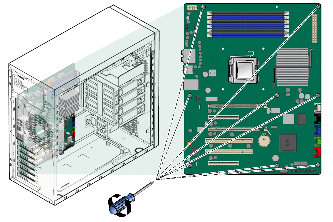
Remove the eight Phillips screws that fasten the motherboard to the chassis (see Figure 3–35).
Figure 3–35 Removing the Eight Motherboard Screws

-
Lift the motherboard away from the chassis.
 Installing the Motherboard
Observe proper antistatic precautions when handling a new motherboard.
-
Remove the new motherboard from its protective antistatic packaging.
-
Position the motherboard so that the back panel I/O connectors (audio and USB ports) are on the upper left.
-
Place the motherboard in the chassis on top of the standoffs.
-
Slide the motherboard toward the chassis back panel until the I/O ports on the upper left side of the motherboard engage the opening in the chassis back panel and the screw holes in the motherboard align with the screw holes in the standoffs.
The screw holes must align.
-
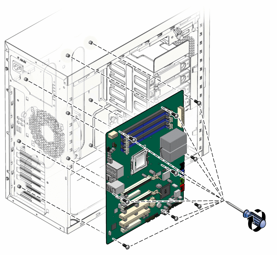
Secure the motherboard to the chassis using the nine Phillips-head screws (see Figure 3–36).
Figure 3–36 Installing the Motherboard

-
Connect the system cables to the motherboard.
-
Install the system fan using the procedure described in the section, Replacing the System Fan.
-
Install the CPU and heat sink using the procedure described in the section, Replacing the Heat Sink and CPU.
-
Install the DIMMs using the procedure described in the section, To Install DIMMs.
-
Install any PCIe cards using the procedures described in the sections:
-
Verify that all system components are securely installed or connected.
-
Close the workstation and prepare for operation using the procedures described in the section, Closing the Workstation and Preparing for Operation.
- © 2010, Oracle Corporation and/or its affiliates
