| C H A P T E R 4 |
|
Connecting Peripherals |
This chapter discusses various methods of connecting peripheral devices to the SunSAI/P adapter and provides sample cable diagrams to aid in constructing the correct cable for your application, including:
|
Note - The cables shown in this section are for information only and are not supplied by Sun Microsystems. |
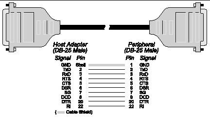
To connect the SunSAI/P board to a modem, use a standard "straight-through" cable (FIGURE 4-1) to connect the modem to one of the DB-25 connectors on the connector box.
|
Note - Shielded cable must be used to remain in compliance with Part 15 of FCC rules. |

Terminals, serial printers, or another computer's serial port are examples of DTE devices. To connect the SunSAI/P board (which is also a DTE device) to another DTE device, you need a null modem cable or adapter.
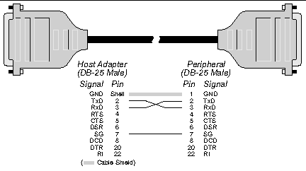
In most cases, serial terminals and printers need only a "three-wire" connection to the SunSAI/P board. The Solaris device driver supports XON/XOFF (software) handshaking, so the only signal lines necessary are Transmitted Data (TxD), Received Data (RxD) and Signal Ground (SG). Cables must be shielded to remain in compliance with FCC certification requirements, and the shield should be connected to Chassis Ground (GND) at both ends of the cable run.
A simple cable for connecting a terminal or a printer to a DB-25 equipped SunSAI/P board is shown in FIGURE 4-2.

|
Note - Shielded cable must be used to remain in compliance with Part 15 of FCC rules. |
The cable shown in FIGURE 4-2 is a three-wire null modem cable--that is, Transmitted Data on one end of the cable is connected to Received Data at the other end, and vice versa.
The male DB-25 end can be plugged directly into most serial terminals and printers without any adapters. The female DB-25 end plugs directly into one of the DB-25 connectors on the connector box assembly.
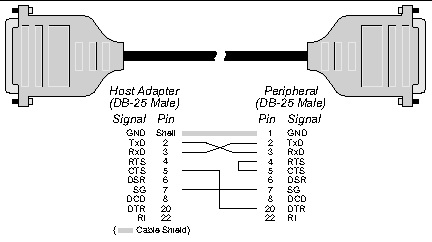
Most terminals and printers use Data Terminal Ready (DTR) for Ready/Busy hardware handshaking. The cable shown in FIGURE 4-3 supports this method.

|
Note - Shielded cable must be used to remain in compliance with Part 15 of FCC rules. |
To use clear to send (CTS)/request to send (RTS) hardware flow control with devices such as modems, we recommend using the options provided by the
/opt/SUNWconn/bin/sitty utility. Use the sitty rtspace and ctspace options instead of the following Solaris stty command options: crtscts, crtsxoff, rtsxoff and/or ctsxon. Refer to the sitty(1m) man page and Chapter 7 of the SunSAI/P User's Guide for more information about the sitty utility.
Copyright © 2007, Sun Microsystems, Inc. All Rights Reserved.