| C H A P T E R 3 |
|
Logging In and Completing the Initial Configuration |
This chapter introduces you to the browser interface and describes how to complete the initial system configuration. It includes the following sections:
For detailed information about the procedures in this chapter, open the online help system by clicking the Help button.
The system provides two interfaces for accessing the configuration and monitoring software:
For information about setting up the remote scripting CLI client, see Installing Remote Management Host Software.
The type of user role you assign to users determines their level of system access. There are three types of user roles (TABLE 3-1).
Multiple users assigned to the administrative or storage roles can be logged in concurrently. However, because storage and administrative users have write privileges, there is a risk of one user's changes overwriting another user's previous changes. Therefore, you should develop policies about who can make changes and how to notify others.
For information on how to change the default password for the storage, admin, or guest roles, see "Changing Passwords" in the online help.
You can access the diagnostic environment and configuration software from a web browser on any host that has network connectivity to the system.
|
Tip - For a list of supported web browsers, see the Sun StorEdge 6920 System Release Notes. |
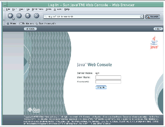
2. Enter the IP address of the system in this format: https://IPaddress:6789
The IPaddress is the IP address of the Sun StorEdge 6920 system. (You assigned the IP address while running the setup script. See Running the Initial Configuration Script.)
|
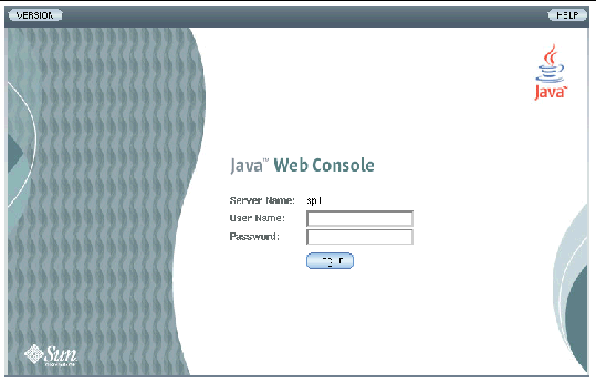
Note - "Server Name" is the name of the Storage Service Processor in the Sun StorEdge 6920 system and is in the form spn, where n is the number entered in Running the Initial Configuration Script; for example, sp1. |
3. Enter the default storage user name and password:
For information about user role and passwords, see About User Roles.
The Java Web Console page is displayed.
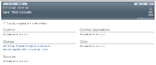
At this point, you are logged in to the system.
5. You can select one of the following applications:
The system displays the appropriate web page, based on your selection.
|
Note - The connection closes automatically if there is no activity for 30 minutes. |
After you log in to the system, the next step is to configure system-wide settings. Complete the following procedures in order to set the initial system information.
Use the General Settings page to add a system description, modify system network settings, update the system time, and change user passwords.
|
Note - You must log in as a storage user to configure system-wide settings. |
1. Click Sun StorEdge 6920 Configuration Service.
The system displays the General Settings page with the network and system settings you specified during the initial configuration (see Running the Initial Configuration Script).
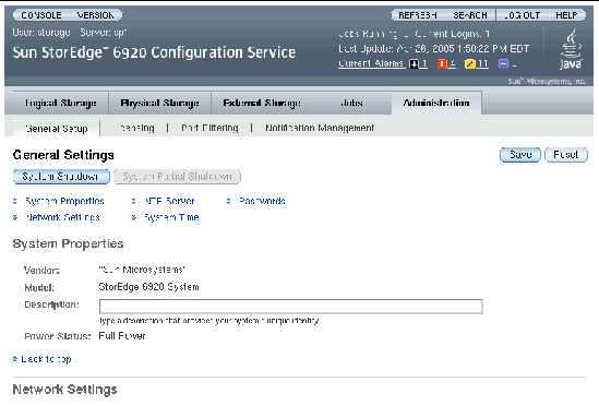
2. In the System Properties Description field, add a description that uniquely identifies your system.
3. Go to the Network Time Protocol (NTP) Server section and enter the IP address of your NTP server, which was provided by your network administrator.
If you do not have an NTP server at this site, check the Disable NTP check box.
4. Go to the System Time section and update the System Time, Date, and Time Zone entries, if necessary.
5. Click Save at the bottom of the page.
You are now ready to configure the initial diagnostics and monitoring settings for the system.
The monitoring and diagnostic software is preconfigured to recognize the hardware configuration of the system, but not specific information about your site. Before using the system, you must specify basic site and email notification information.
|
Note - You can be logged in as a storage or admin user to configure diagnostic and monitoring settings. |
1. Click Console to return to the Java Web Console page.
2. Click Sun Storage Automated Diagnostic Environment.
The Site Information page is displayed.
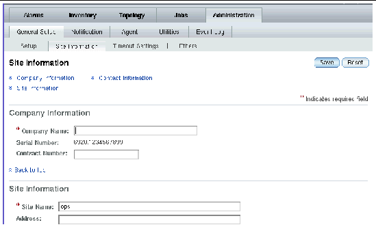
3. Fill in all mandatory Site Information entries as denoted by red asterisks, and then click Save.
If you need a description of any of the fields, click the Help button on the Site Information page.
4. To set up email or pager notifications:
a. Click Administration > Notification > Email.
The Email Notification page is displayed.
b. Click New to add a new email or pager notification address.
The Add Email Notification Page is displayed.
c. Enter each email or pager notification address you want to add, and click Save.
For information about the parameters on the Add Email Notification page, click the Help button on that page.
5. To test a notification email address:
a. Click Administration > Notification > Setup.
The Notification Setup page is displayed.
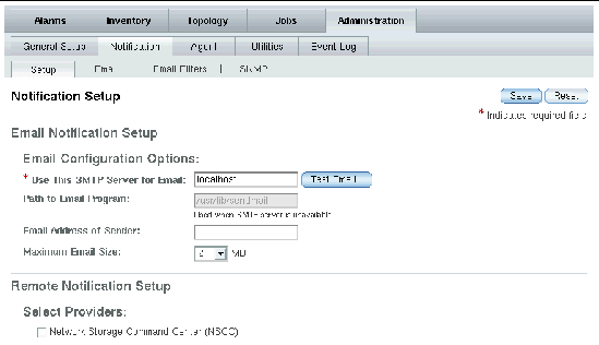
b. Enter the name of the SMTP server in the * Use this SMTP server for Email field. Click Test Email.
The Send Test Email page is displayed.
c. Fill in the *To field and type a brief message in the Message field.
A confirmation message appears if the test email is sent successfully.
e. Click Close to close the Send Test Email page.
6. To set up SNMP traps, click Administration > Notification > SNMP, and enter the following information:
a. Enter the IP name or address of the new SNMP recipient. You can provide information for up to five IP addresses.
b. Select the minimum alarm level for which SNMP notifications are to be sent to the SNMP recipient. The options are Down, Critical, Major, and Notice.
7. To enable remote notification:
a. Click Administration > Notification > Setup.
The Notification Setup page is displayed.
b. Select the check box for each remote notification provider you want to enable.
The Sun StorEdge 6920 system supports the following providers:
c. To activate the NSCC provider, enable or disable email encryption by clicking Yes or No.
d. To activate the Sun StorEdge Remote Response provider, enter the frequency (in hours) with which you want to check the communication link to the Sun StorEdge Remote Response provider. Typical values are 6, 12, and 24 hours.
A message indicates that the notification setup was saved.
An alarm is generated if any problems occurred with the hardware during installation. To get information about any current alarms:
The Alarm Summary page is displayed.
2. Click the Details link to get more information about an alarm.
The Alarm Details provides alarm details, a probable cause, and a recommended action for the selected alarm.
3. If you need help with any of the information on the page, click the Help button.
|
Note - If you added an expansion cabinet, your next step is to set the IP addressess of the arrays. If you did not add an expansion cabinet, you can start to connect hosts to the service panel, as described in Chapter 4. |
After you add an expansion cabinet to the Sun StorEdge 6920 system, you must identify the arrays to the system by setting the array addresses and updating the system inventory. Perform the following steps so that the arrays in the expansion cabinet are recognized by the system.
1. If you are not already logged in, log in to the system as a storage user:
user name: storage password:!storage
2. On the Java Web Console page, click Storage Automated Diagnostic Environment.
The system displays the Alarm Summary page.
3. Click Administration > General Setup > Ethers.
The system displays the Ethers page, which lists the names and corresponding IP addresses of all standard and optional components that make up the Sun StorEdge 6920 system.
4. Locate the MAC address of the master controller of each array in the expansion cabinet, and enter that MAC address in the appropriate MAC address field.
The MAC addresses are located on a sticker on the back panel of each controller tray in an array. The bottom tray in the array is the master controller of the array.
The MAC addresses for the arrays in the expansion cabinet correspond to IP addresses 192.168.0.50 (starting with the array at the bottom of the expansion cabinet) through 192.168.0.55.
The system runs a script that associates the MAC address of each array with the corresponding IP address to identify the array to the system. A message appears after the Ether file has been updated.
6. Power cycle the expansion cabinet.
To power cycle all arrays in the expansion cabinet, insert the key into the power sequencer in the front bottom of the expansion cabinet and turn the key to the Off position. When you do this, the array battery backup comes on and allows the write cache to flush. To determine that all arrays are completely shut down, verify that all LEDs on the back of all trays are turned off. After approximately 30 seconds, turn the key back to the On position to power on the expansion cabinet.
The Rack Inventory page is displayed.
8. In the Expansion Rack section, select Generate New Inventory.
The Generate Inventory page is displayed.
After the new inventory has been generated, check whether the list include all expected devices. If any devices are missing, repeat this procedure starting with Step 4.
10. Click Save to save the new inventory.
After you complete the steps in this chapter, you will have done the following:
Your next step is to connect data hosts to the service panel, as described in Connecting Data Hosts.
Copyright © 2005, Sun Microsystems, Inc. All Rights Reserved.