| C H A P T E R 2 |
|
Mounting in Sun Cabinets |
This chapter explains how to mount Sun StorEdge 3000 Family 1U array by using universal, adjustable mounting brackets for depth ranges between 24 to 36 inches (60.96 to 91.44 cm).
Two configurations exist for Sun cabinets:
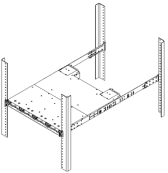
Refer to FIGURE 2-4 during installation.
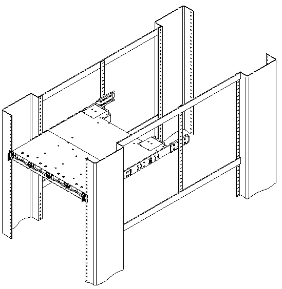
Refer to FIGURE 2-9 during installation.
Before mounting the Sun StorEdge 3000 Family 1U array into a 19-inch wide cabinet, check that you have all the rackmount kit components (TABLE 2-1) listed for the rack installation kit you are installing.
Review Section 1.2, One-Person Installation Requirements and Section 1.3, Reviewing the Tools before rackmounting the array.
Refer to the parts list in TABLE 2-1 and the illustration in FIGURE 2-1 during installation. The table lists the major components and fasteners required to install an array into the cabinet.

|
Caution - Do not use any power tools with any procedures. Power tools can strip or damage connections. |
1. Determine the position at which the array will be installed.
Install the first array at the bottom of the rack, and install each subsequent chassis above the previous one.
|
Note - Keep all hardware items in plastic bags until you are ready to use them. This will enable you to correctly identify the screws and avoid confusion. |
2. Before rackmounting, be sure to check your site location and confirm that you have cables with adequate lengths to connect to servers and to power outlets.
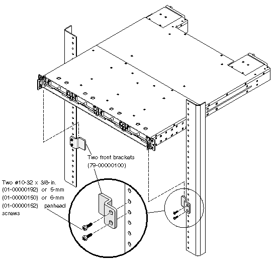
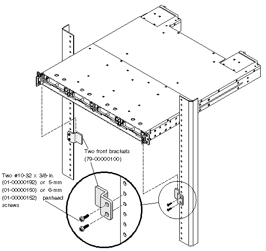
3. (Optional). Before you mount the unit, screw the front support brackets (79-00000100) into position on the rack face. The front support brackets enable one person to easily position and support the front of the unit in the rack.
a. Attach each front bracket to the rack face (See FIGURE 2-3):
To connect the front brackets (79-00000100), use a minimum of two screws per front bracket.
Use the appropriate screws for the rack:
4. Remove the bezel (the front faceplate) and the two plastic ear caps from the front of the chassis.
To remove a plastic ear cap (both caps are removed the same way):
a. Grasp both sides of the cap.
b. With minimal force, pull the cap straight out from the array until it disengages.
|
Note - Alternate screws can be used with the appropriate racks: 5-mm panhead screws (front and back), or 6-mm sockethead screws (front) and 6-mm panhead screws (back). |
|
Note - Keep all hardware items in plastic bags until you are ready to use them. This will enable you to correctly identify the screws and avoid confusion. |
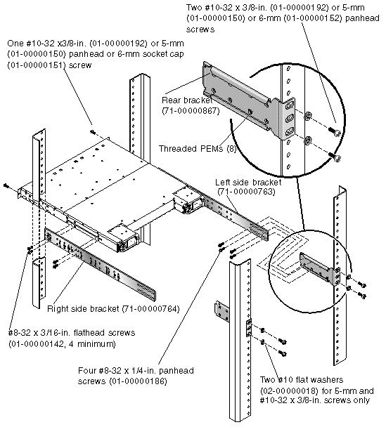
5. Attach the side brackets to the left and right sides of the chassis.
Attach up to eight #8-32 x 3/16-inch flathead machine screws (01-00000142) on each side to allow some adjustment to the placement. Make sure you use at least four screws on each side (six screws per side is recommended).

|
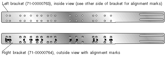
Note - The right and left side brackets may look identical, but they are slightly different. Each side bracket is clearly stamped with numbers. Position the side brackets with the number side of the bracket facing out and the holes closest to the edge of the bracket mounted to the bottom of the chassis. See TABLE 2-1 for the rack kit contents and part numbers. |
a. Use the alignment marks (depth in inches) stamped into the side brackets to position the brackets and screws.
There are markings for several depths: 24, 24.5, 26, 27, 28, 30, 32, 34, and 36 inches.
Determine the depth you require and align the last (rearmost) alignment mark for each depth on the side bracket to the last mounting holes on the chassis.
Make sure the alignment mark corresponding to the depth you want lines up with the top and bottom threaded holes on the side of the chassis closest to the rear.
b. Insert the first two screws on each side through the side bracket slots above and below the appropriate alignment mark (24, 24.5, 26, 27, 28, 30, 32, 34, or 36) and into the last pair of rear threaded holes in the chassis.
In the illustration below, the 34-inch alignment mark is positioned above and below the last pair of rear threaded holes. This positions the array for a 34-inch deep rack.
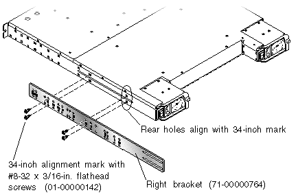
c. Insert up to six other screws through the side bracket slots into the other threaded holes in the chassis. Use a minimum of four screws for each side bracket.
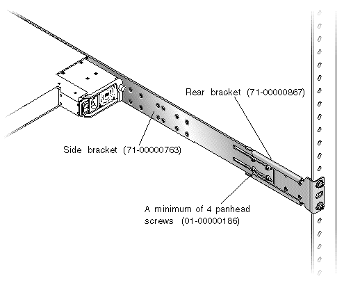
6. Attach the rear brackets to the rear vertical posts using a total of four screws and four washers (two screws to attach each bracket to a post). (See FIGURE 2-4.)
Attach each rear bracket with two of the appropriate screws for the posts:
|
Note - Not all racks allow mountings in the location shown in the preceding figure. |
7. Lift the chassis and slide the side brackets into the rear brackets, which are attached to the rear posts. (See FIGURE 2-7)
Adjust the depth of these brackets so that the rear slotted cutouts on the side brackets align with the four PEM nuts in the rear brackets.
a. Insert a minimum of four each and up to a total of eight #8-32 x 1/4-inch panhead screws (01-00000186) through the side bracket slots and through the rear bracket holes.
8. Attach and secure the array's front mounting ears with two appropriate screws (one screw into each ear, as shown in FIGURE 2-4):
9. Remount all drives and power/fan modules into the array.
10. If you mounted the unit using the optional front support brackets, remove them from the rack face using a standard screwdriver.
11. Reattach the two plastic ear caps and the bezel onto the front of the chassis.
Each plastic cap is replaced the same way, but be sure the cap with the LED labels on the right ear.
a. Align the inside round notches of the cap with the round cylindrical posts (ball studs) on the ear.
b. Push the top and bottom of the ear cap onto the ear, pressing in toward the center of the array.
c. Continue pushing the top and bottom of the ear cap onto the ear until the ear cap snaps in flush.
Do not use force when placing a cap on an ear.

|
Caution - Be careful to avoid "wedging" the reset button below the LEDs on the right ear when you replace the plastic cap over it. |
d. Insert the bezel swing arms into the chassis ear holes.
e. Lift the bezel into position and press it onto the front of the chassis until it is flush with the front.
f. Use the key to lock both bezel locks.
12. Connect power cables to the chassis, power on, and check for proper operation of the LEDs.
For details on powering on and checking LEDs, see Chapter 4.
Refer to the Sun StorEdge 3000 Family Installation, Operation, and Service Manual for your array to see more information about cable connections and LED functionality.
Be sure to review Section 1.2, One-Person Installation Requirements and Section 1.3, Reviewing the Tools before rackmounting the array.
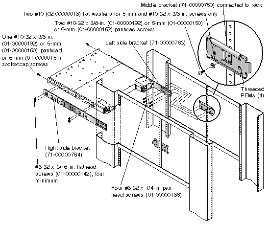
Refer to the parts list in TABLE 2-1 and the illustration in FIGURE 2-2 during installation. The table lists the major components and fasteners required to install an array into the cabinet.

|
Caution - Do not use any power tools with any procedures. Power tools can strip or damage connections. |
1. Determine the position at which the array will be installed.
Install the first array at the bottom of the rack, and install each subsequent chassis above the previous one.
|
Note - Keep all hardware items in plastic bags until you are ready to use them. This will enable you to correctly identify the screws and avoid confusion. |
2. Before rackmounting, be sure to check your site location and confirm that you have cables with adequate lengths to connect to servers and to power outlets.
3. (Optional). Before you mount the unit, screw the front support brackets (79-00000100) into position on the rack face. The front support brackets enable one person to easily position and support the front of the unit in the rack.
a. Attach each front bracket to the rack face (See FIGURE 2-8):
To connect the front brackets (79-00000100), use a minimum of two screws per front bracket.
Use the appropriate screws for the rack:
4. Remove the bezel (the front faceplate) and the two plastic ear caps from the front of the chassis.
To remove a plastic ear cap (both caps are removed the same way):
a. Grasp both sides of the cap.
b. With minimal force, pull the cap straight out from the array until it disengages.
|
Note - Alternate screws can be used with the appropriate racks: 5-mm panhead screws (front and back), or 6-mm socket cap screws (front) and 6-mm panhead screws (back). |
5. Attach the side brackets to the left and right sides of the chassis.
Attach up to eight #8-32 x 3/16-inch flathead machine screws (01-00000142) on each side to allow some adjustment to the placement. Make sure you use at least four screws.
|
Note - The right and left side brackets may look identical, but they are slightly different. Each side bracket is clearly stamped with numbers. Position the side brackets with the number side of the bracket facing out and the holes closest to the edge of the bracket mounted to the bottom of the chassis. See TABLE 2-1 for the rack kit contents and part numbers. |
a. Use the alignment marks (depth in inches) stamped into the side brackets to position the brackets and screws.
There are markings for several depths: 24, 24.5, 26, 27, 28, 30, 32, 34, and 36 inches.
Determine the depth you require, and align the last alignment mark on the side bracket with the last mounting holes on the chassis.
Make sure the alignment mark corresponding to the depth you want lines up with the top and bottom threaded holes on the side of the chassis closest to the rear.
b. Insert the first two screws on each side through the side bracket slots above and below the appropriate alignment mark (24, 24.5, 26, 27, 28, 30, 32, 34, or 36) and into the last pair of rear threaded holes in the chassis.
In FIGURE 2-11 the alignment mark is positioned above and below the last pair of rear threaded holes. This positions the array for a 24.5-inch deep center rail for mounting the middle bracket.
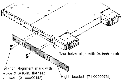
c. Insert up to six other screws through the side bracket slots into the other threaded holes in the chassis.
6. Attach the middle brackets to the rack center posts using one screw per post. (See FIGURE 2-9).
a. Use one of the following screws:
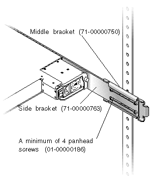
7. Lift the chassis and slide the side brackets into the middle brackets, which are attached to the center posts.
Adjust the depth of these brackets so that the slotted cutouts on the side brackets align with the four PEM nuts in the middle brackets.
8. Attach each side bracket to a middle bracket (see FIGURE 2-12):
To connect the middle brackets and side brackets of a 24-inch to 36-inch deep rack, use a minimum of four screws each and up to a total of four #8-32 x 1/4-inch panhead screws (01-00000186).
9. Attach and secure the array's front mounting ears with two appropriate screws (one screw into each ear):
10. Remount all drives and power/fan modules into the array.
11. If you mounted the unit using the optional front support brackets, remove them from the rack face using a standard screwdriver.
12. Reattach the two plastic ear caps and the bezel onto the front of the chassis.
Each plastic cap is replaced the same way, but be sure the cap with the LED labels on the right ear.
a. Align the inside round notches of the cap with the round cylindrical posts (ball studs) on the ear.
b. Push the top and bottom of the ear cap onto the ear, pressing in toward the center of the array.
c. Continue pushing the top and bottom of the ear cap onto the ear until the ear cap snaps in flush.
Do not use force when placing a cap on an ear.

|
Caution - Be careful to avoid "wedging" the reset button below the LEDs on the right ear when you replace the plastic cap over it. |
d. Insert the bezel swing arms into the chassis ear holes.
e. Lift the bezel into position and press it onto the front of the chassis until it is flush with the front.
f. Use the key to lock both bezel locks.
13. Connect power cables to the chassis, power on, and check for proper operation of the LEDs.
For details on powering on and checking LEDs, see Chapter 4.
Copyright © 2006, Dot Hill Systems Corporation and others. All rights reserved.