| Skip Navigation Links | |
| Exit Print View | |

|
SPARC T3-1B Server Module Topic Set |
Front and Rear Panel Components
Plan Communication With the Server Module During Installation
Optional Component Installation
Modular System Chassis Preparation
Insert the Server Module Into the Chassis
Communicating With the Server Module During Startup
Monitor the Diagnostic Messages
Powering On the Server Module for the First Time
Initial Power-On Task Overview
Power On the System for the First Time
Install Oracle Solaris Software From the Network
Oracle Solaris Configuration Settings
Assign a Static IP Address to the Service Processor
Understanding System Administration Resources
Platform-Specific Oracle ILOM Features
Oracle VM Server for SPARC Overview
Hardware Management Pack Overview
Source for Downloading Hardware Management Pack Software
Hardware Management Pack Documentation
Display the Oracle ILOM -> Prompt
Reset the Server From the Oracle Solaris OS
Reset the Server From Oracle ILOM
Reset the SP to Default Values
Important Hardware RAID Guidelines
Disk Zones for SPARC T3-1 Servers With Sixteen-Disk Backplanes
Displaying Disk Zone Information
Enabling and Disabling Disk Zoning In the Field
Prepare to Use the FCode Utility
Hot Spare Drives in RAID Volumes (LSI)
Determining If a Drive Has Failed
RAID Drive Replacement Strategies
Changing Server Identification Information
Change Customer FRUdata Information
Change System Identifier Information
Restore Host Power State at Restart
Specify Host Power State at Restart
Disable or Re-Enable Power-On Delay
Specify Parallel Boot of the SP and Host
Configure Host Behavior With the Keyswitch State
Disable or Re-Enable Network Access to the SP
Display the DHCP Server IP Address
Using an In-band Connection to the SP
Configure the Host Boot Mode of Oracle VM Server for SPARC
Change the Host Boot Mode Behavior at Reset
Manage the Host Boot Mode Script
Display Host Boot Mode Expiration Date
Override OpenBoot PROM Settings to Reset the Server
Configuring Server Behavior at Restart
Specify Behavior When the Host Resets
Specify Behavior When the Host Stops Running
Specify Behavior at Boot Timeout
Specify Behavior if Restart Fails
Specify Maximum Restart Attempts
Enabling Automatic System Recovery
Identifying WWN-Designated SAS2 Devices
probe-scsi-all Output Example (SPARC T3-1, Eight-Disk Backplane)
probe-scsi-all Output Example (SPARC T3-1, Sixteen-Disk Backplane)
probe-scsi-all Output Example (SPARC T3-4)
Identify a Disk Slot Using probe-scsi-all (OBP)
Identify a Disk Slot Using prtconf (Oracle Solaris, Onboard Controllers)
Identify a Disk Slot Using prtconf (Oracle Solaris, Single Initiator)
WWN Syntax in an OS Installation on a Specific Device
WWN Syntax in an OS Installation on a RAID Volume
Front and Rear Panel Components
Interpreting Log Files and System Messages
Managing Faults (Oracle Solaris PSH)
Managing Components (ASR Commands)
Checking if Oracle VTS Software Is Installed
Find the Modular System Serial Number
Find the Server Module Serial Number
Removing the Server Module From the Modular System for Service
Clear the Fault and Verify the Functionality of the Replacement DIMM
Servicing a Service Processor Card
Remove the Service Processor Card
Install the Service Processor Card
Replacing the Server Module Enclosure Assembly
Transfer Components to Another Enclosure Assembly
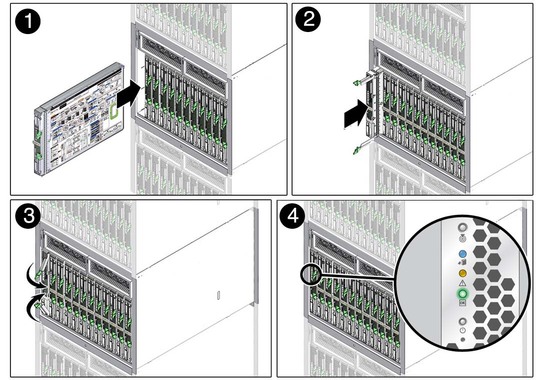
 | Caution - Insert a filler panel into an empty modular system slot within 60 seconds of server module removal to ensure proper chassis cooling. |
 | Caution - Hold the server module firmly with both hands so that you do not drop it. The server module weighs approximately 17 pounds (8.0 kg). |
When the modular system is operating, you must fill every slot with a filler panel or a server module within 60 seconds.

Once installed, the following server module activities take place:
Standby power is applied.
The front panel LEDs blinks three times, then the green OK LED on the front panel blinks for a few minutes.
Oracle ILOM is initialized on the server module SP and ready to use, but the server module host is not started.