This chapter provides an overview of the Sun Storage 6180 array. It contains the following sections:
Product Overview
The Sun Storage 6180 array is a high-performance, enterprise-class, full 8 Gigabit per second (Gb/s) I/O Fibre Channel solution (with backend loop speeds of 2 or 4 Gb/s) that combines outstanding performance with the highest reliability, availability, flexibility, and manageability.
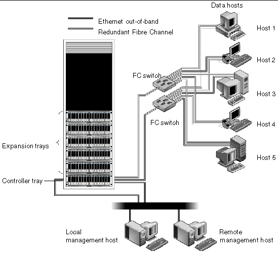
The Sun Storage 6180 array is modular, rackmountable and scalable from a single dual-controller tray (1x1) configuration to a maximum configuration of 1x7 with six additional expansion trays behind one controller tray (see FIGURE 1-1).
This section contains an overview of the Sun Storage 6180 array hardware and software.
FIGURE 1-1 Sun Storage 6180 Array Product Overview
 [ D ]
[ D ]
Hardware Overview
The Sun Storage 6180 array is a modular storage device that can scale from one controller tray to an array with a maximum of seven trays, consisting of one controller tray and six expansion trays. Each 4-port controller can support up to 64 disk drives; each 8-port controller or expansion tray can support up to 112 disk drives.
The Sun Storage 6180 array can be installed in the Sun Rack 900/1000, the Sun Rack II, or Sun StorEdge Expansion cabinets.
This section describes the main components of the Sun Storage 6180 array controller and expansion trays.
Controller Tray Component Configurations
A controller tray contains two redundant array of independent disks (RAID) controllers, which operate independently and provide failover capability for the data and management paths. The controller tray is configured for Fibre Channel (FC) or Serial Advanced Technology Attachment (SATA) II disk drives and provides RAID functionality, caching, and disk storage.
TABLE 1-1 Sun Storage 6180 Array Controller Tray Configuration
|
Description
|
Quantity
|
|
FC RAID controllers
|
2
|
|
FC/SATA II disk drives
|
5 -16, 4-Gb or 2-Gb drives per tray with circuitry to support operation in either 4- or 2-Gbit/second environments
|
|
Ethernet ports for management host connections
|
4 per tray (2 per controller)
|
|
8 /4/2 Gbps FC host ports with SFPs
|
4 per tray (2 per 4-port controller)
8 per tray (4 per 8-port controller)
|
|
4/2 Gbps FC expansion ports
|
4 (2 per controller)
|
|
Power supply/fan assemblies
|
2 per tray
|
|
Battery backup compartments
|
2 per tray
|
Controller Tray
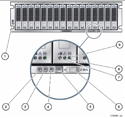
FIGURE 1-2 Controller Tray (Front View)
 [ D ]
[ D ]
Figure Legend
|
1
|
Grounding strap connector
|
6
|
Rate select switch
|
|
2
|
Locate
|
7
|
Service action allowed
|
|
3
|
Service action required
|
8
|
Service action required
|
|
4
|
OK/Power
|
9
|
OK/Power
|
|
5
|
Alarm cancel
|
|
|
Controller Tray LEDs and Components
| Note - A tray LED icon may not be visible unless the LED is illuminated.
|
TABLE 1-2 Controller Tray LEDs and Components
|
LED/Component
|
Description
|
|
Drive LEDs
|
Service Action Allowed

|
Steady blue indicates that service action can be taken on the drive without adverse consequences. Off indicates that the drive is engaged and service cannot be implemented.
|
Service Action Required

|
Steady amber indicates that the drive requires service. Off indicates that the drive does not require service.
|
OK

|
Steady green indicates that power is applied to the drive and the drive is functioning normally. Off indicates that power is not applied to the drive. Flash indicates that normal activity is in progress.
|
|
Tray LEDs
|
Locate

|
Steady white identifies the tray after initiation from the management station.
|
Service Action Required

|
Steady amber indicates that the tray requires service. Off indicates that the tray does not require service.
|
OK/Power

|
Steady green indicates that power is applied to the tray and the tray is functioning normally. Off indicates that power is not applied to the tray. Flash indicates that normal activity is in progress
|
|
Tray Components
|
Alarm Cancel button

|
Reserved for canceling audio alarm functionality that is not currently activated. Use the management software to review alarms and events.
|
Rate Select switch

|
When the switch is in the left position, the link rate for the tray is 4 Gbits/second; When the switch is in the right position, the link rate for the tray is 2 Gbits/second. Set all tray switches to match the link rate of the drive with the lowest link rate of any tray in the array.
Note - If the data rate switch is changed, a power cycle is required.
|
Grounding strap connector

|
Use this connector to connect a grounding strap to the tray before handling the tray or its components.
|
Controller Tray Ports
FIGURE 1-3 4-Port and 8-Port Controller Tray (Rear View)
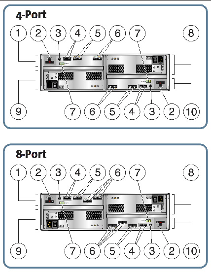
Figure Legend
|
1
|
Controller A
|
6
|
Fibre Channel data host ports
|
|
2
|
Battery backup compartment
|
7
|
ID/Diagnostic display (7-segment)
|
|
3
|
Serial port (diagnostic use)
|
8
|
Power supply A
|
|
4
|
Ethernet management ports
|
9
|
Power supply B
|
|
5
|
Fibre Channel expansion ports
|
10
|
Controller B
|
DC Power Option
FIGURE 1-4 shows the location of the DC power connector and DC power switch at the back of the DC power option controller tray.
FIGURE 1-4 Controller Tray (Rear View) DC Power Option
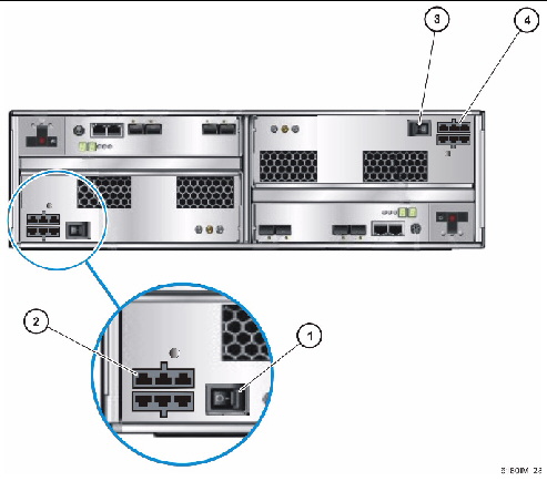
Figure Legend
|
Power Supply B
|
Power Supply A
|
|
1
|
DC power switch
|
3
|
DC power switch
|
|
2
|
DC power connectors
|
4
|
DC power connectors
|
Controller Tray Ports and Components
TABLE 1-3 Controller Tray Ports and Components
|
Ports/Switches
|
Description
|
|
Host ports
(Ch 1 - Ch4)
|
Four 4-, or 2-Gbit/second FC Small Form-factor Plug-in (SFP) ports. Ch4 host port is reserved for remote replication (if remote replication is licensed and activated; otherwise, Ch4 is available for host port use).
Note: 1 Gbit/second operation is supported for legacy equipment only.
|
|
Ethernet ports
(1 and 2)
|
RJ-45 Ethernet ports. Ethernet port 1 is used for out-of-band management of the RAID controller. An internal Ethernet device provides standard 10 Mbits/second and 100 Mbits/second full-duplex connectivity. Ethernet port 2 has limited functionality and is reserved for future use.
|
|
Expansion ports
(P1 and P2)
|
4- or 2-Gbit FC ports used to connect to the drive channel device and expansion trays.
|
|
Serial port
|
Port that allows terminal access for display or configuration of the IP addresses for the array, and for recovery of a lost password for the array.
|
|
Power supplies
(DC power optional)
|
For each controller tray, two power supplies with battery backup. The power supplies provide redundant power to both controllers. If one power supply fails, both controllers are powered by the remaining power supply.
|
|
Battery backup compartments
|
For each controller, a battery backup to maintain the integrity of the controller’s data cache for up to 72 hours in the event of power loss to both controller tray power supplies. See Battery Backup Compartments for more information on the battery backup compartments.
|
Controller Tray LEDs and Indicators
FIGURE 1-5 Controller Tray (Rear View) LEDs and Indicators
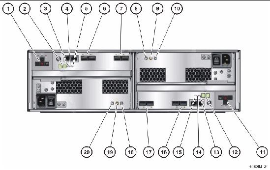
Figure Legend
|
1
|
Battery backup compartment
|
11
|
Battery backup compartment
|
|
2
|
ID/Diag display
|
12
|
ID/Diag display
|
|
3
|
Cache active indicator
|
13
|
Cache active indicator
|
|
4
|
Service required indicator
|
14
|
Service required indicator
|
|
5
|
Service allowed indicator
|
15
|
Service allowed indicator
|
|
6
|
FC expansion port rate indicators
|
16
|
FC expansion port rate indicators
|
|
7
|
FC host port rate indicators
|
17
|
FC host port rate indicators
|
|
8
|
DC power indicator
|
18
|
DC power indicator
|
|
9
|
Service required indicator
|
19
|
Service required indicator
|
|
10
|
Service allowed indicator
|
20
|
Service allowed indicator
|
TABLE 1-4 describes the LEDs and indicators at the rear of the controller tray.
TABLE 1-4 Controller Tray LEDs and Indicators
|
LED/Indicator
|
Description
|
|
Power Supply LEDs
|
DC

|
On indicates that the correct DC power is being output from the controller power supply.
|
Service Action Required

|
Steady amber indicates that the power supply requires service. Off indicates that the power supply does not require service.
|
Service Action Allowed

|
Steady blue indicates that service action can be taken on the power supply without adverse consequences. Off indicates that the power supply is engaged and service action should not be implemented.
|
AC

|
On indicates that AC power is being supplied to the controller power supply.
|
|
Controller LEDs
|
|
ID/Diag display
|
Seven-segment readouts indicate the ID of the tray and fault diagnostic status codes. See LED Status Codes for definitions of the codes.
|
Cache Active

|
Steady green indicates that data is in the cache. Off indicates that all data has been written to disk and the cache is empty.
|
Service Action Required

|
Steady amber indicates that the controller requires service. Off indicates that the controller does not require service.
|
Service Action Allowed

|
Steady blue indicates that service action can be taken on the controller without adverse consequences. Off indicates that the controller is engaged and service action should not be implemented.
|
|
Controller Indicators
|
Host Port Rate

|
The LEDs display the host port link rate:
- LED 2 On = 2 Gbits/second
- LED 4 On = 4 Gbits/second
- LED 2 and 4 On = 8 Gbits/second
|
Expansion Port Rate

|
The combined display indicates the expansion port link rate for the tray:
- LED 4 On, LED 2 On - 4 Gbits/second
- LED 4 Off, LED 2 On - 2 Gbits/second
|
Expansion Port Bypass

|
Steady amber indicates that no valid device is detected and that the drive port is bypassed. Off indicates that there is no small form factor plug-in (SFP) transceiver installed or that the port is enabled.
|
|
Ethernet Link Activity
(on upper left-side of Ethernet connector)
|
Steady green indicates that there is an active connection. Off indicates that there is not an active connection.
|
|
Ethernet Link Speed
(on upper right-side of Ethernet connector)
|
Steady green indicates that the there is a 100BaseTX connection to the port. Off (when Ethernet Status LED is on) indicates that there is a 10BaseT connection to the Ethernet port.
|
Disk Drives and Tray Capacity
TABLE 1-5 lists the size, spindle speed, type, interface speed, and tray capacity for supported Fibre Channel (FC) and Serial Advanced Technology Attachment (SATA) disk drives for the Sun Storage 6180 array. Additional legacy drives might also be supported with this product.
| Note - All disk drives supported in the Sun Storage 6140 array are supported in the Sun Storage 6180 array.
|
TABLE 1-5 Supported Disk Drives
|
Drive
|
Description
|
|
FC, 73G15K
|
73-Gbyte 15,000-RPM FC drives
(4 Gbits/sec); 1168 Gbytes per tray
|
|
FC, 146G10K
|
146-Gbyte 10,000-RPM FC drives
(4 Gbits/sec); 2336 Gbytes per tray
|
|
FC, 146G15K
|
146-Gbyte 15,000-RPM FC drives
(4 Gbits/sec); 2336 Gbytes per tray
|
|
FC, 300G10K
|
300-Gbyte 10,000-RPM FC drives
(4 Gbits/sec): 4800 Gbytes per tray
|
|
FC, 300G15K
|
300-Gbyte 15,000-RPM FC drives
(4 Gbits/sec); 4800 Gbytes per tray
|
|
FC, 400G10K
|
400-Gbyte 10,000-RPM FC drives
(4 Gbits/sec): 6400 Gbytes per tray
|
|
FC, 450G15K
|
450-Gbyte 15,000-RPM FC drives
(4 Gbits/sec); 7200 Gbytes per tray
|
|
SATA-2, 500G7.2K
|
500-Gbyte 7,200-RPM SATA drives
(3 Gbits/sec); 8000 Gbytes per tray
|
|
FC, 600GB15K, Encryption Capable
|
600-Gbyte 15,000-RPM FC drives
Encryption Capable
(4 Gbits/sec); 9600 Gbytes per tray
|
|
SATA-2, 750G7.2K
|
750-Gbyte 7,200-RPM SATA drives
(3 Gbits/sec); 12000 Gbytes per tray
|
|
SATA-2, 1T7.2K
|
1-Tbyte 7,200-RPM SATA drives
(3 Gbits/sec); 16000 Gbytes per tray
|
|
SATA-2, 2TB7.2K
|
2-Tbyte 7,200-RPM SATA drives
(3 Gbits/sec); 32000 Gbytes per tray
|
Tray Capacity
- For controller trays with four host ports, up to three expansion trays can be added.
- For controller trays with eight host ports, up to six expansion trays can be added.
- The array configuration supports unlimited global hot spare drives, and each spare can be used for any disk in the array configuration.
Battery Backup Compartments
The controller tray has a battery backup compartment for each controller in which a battery is housed for power backup.
FIGURE 1-6 Battery Backup LEDs
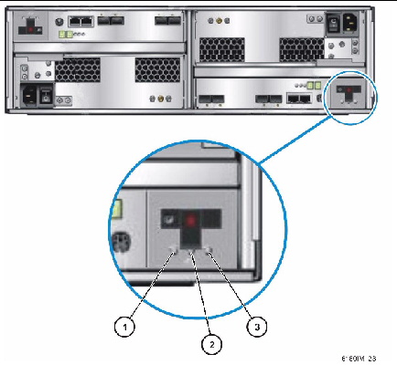
Figure Legend
|
1
|
Service action allowed LED
|
3
|
Battery status
|
|
2
|
Service action required LED
|
|
|
TABLE 1-6 describes the LEDs on the rear of each battery backup compartment.
TABLE 1-6 Battery Backup Compartment LEDs
|
LED/Indicator
|
Description
|
Service action allowed

|
Service action allowed: the battery may be removed when this LED is on.
When the LED is off, the battery is engaged and should not be removed or disconnected.
Data availability may be interrupted if the Service action required LED is on and the Service action allowed LED is off. Refer to your storage management software to determine what must be done.
|
Service action required

|
Service action required: the battery requires replacement when this LED is on.
When the LED is off, the battery does not require replacement.
|
Battery status

|
Steady green indicates that the battery is fully charged. A slow blink indicates that the battery is charging. Off indicates that the battery is discharged or off.
|
Expansion Tray
The CSM200 expansion tray provides from 5 to 16 additional FC or Serial Advanced Technology Attachment (SATA) II drives.An expansion tray is cabled directly to a controller tray and cannot operate independently.
| Note - The CSM200 is the only expansion tray model supported by the Sun Storage 6180 array. Refer to “Installing Firmware for Additional Expansion Modules” in the Common Array Manager Release Notes, v.6.6.0 or higher, for more information on the procedure to upgrade trays without data.
|
TABLE 1-7 describes the expansion tray configuration. Check the latest Sun Storage 6180 Array Release Notes to verify the currently supported configuration.
TABLE 1-7 Sun Storage 6180 Array Expansion Tray
|
Description
|
Quantity
|
|
FC or SATA II disk drives
|
FC hard disk drives: 73G15K, 146G10K, 146G15K, 300G10K, 400G10K, 450G10K, 600GB15K Encryption Capable
|
Five to sixteen 4-Gbit/second drives
|
|
|
SATA II hard disk drives: 500G7.2K, 750G7.2K, 1T7.2K, 2TB7.2K
|
Five to sixteen 3-Gbit/second drives with circuitry to support operation in either 4- or 2-Gbit/second environments.
|
|
Drive expansion ports
|
|
2 pairs per controller. One pair is for current use; an additional port pair (per controller) is reserved for future use. Ports 2A and 2B are disabled in firmware.
|
|
Power supply/fan assemblies
|
2
|
|
Note - Refer to the Release Notes for the most current drive types.
|

|
Caution - To add expansion trays with existing stored data to the 6180 controller tray, contact your service representative for assistance to avoid data loss.
|
FIGURE 1-7 illustrates the ports and components at the rear of the expansion tray.
FIGURE 1-7 Expansion Tray (Rear View) Ports and Components
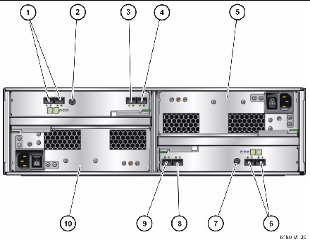
Figure Legend
|
1
|
Reserved expansion ports (2A & 2B)
|
6
|
Reserved expansion ports (2A & 2B)
|
|
2
|
Serial port
|
7
|
Serial port
|
|
3
|
Expansion port 1B (Out)
|
8
|
Expansion port 1B (Out)
|
|
4
|
Expansion port 1A (In)
|
9
|
Expansion port 1A (In)
|
|
5
|
Power supply A
|
10
|
Power supply B
|
TABLE 1-8 describes the ports and components at the rear of the expansion tray.
TABLE 1-8 Expansion Tray Ports and Components
|
Ports/Switches/LEDs
|
Description
|
|
Expansion ports
1A (In), 1B (Out)
|
Two 4- or 2-Gbit FC ports used to connect to an array controller and/or additional expansion trays.
|
|
Serial port
|
Not used in the expansion trays.
|
|
Power supplies
|
For each expansion tray, two power supplies that provide redundant power to the tray. If one power supply fails, the tray is powered by the remaining power supply.
|
|
Reserved expansion ports 2A and 2B
|
Reserved for future use.
|
FIGURE 1-8 illustrates the LEDs at the rear of the expansion tray.
FIGURE 1-8 Expansion Tray (Rear View) LEDs and Indicators
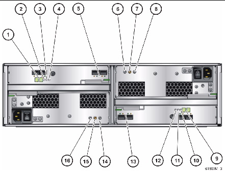
Figure Legend
|
1
|
ID/Diag display
|
9
|
ID/Diag display
|
|
2
|
Locate
|
10
|
Locate
|
|
3
|
Service action required
|
11
|
Service action required
|
|
4
|
Service action allowed
|
12
|
Service action allowed
|
|
5
|
Expansion port link rate indicators
|
13
|
Expansion port link rate indicators
|
|
6
|
DC
|
14
|
DC
|
|
7
|
Service action required
|
15
|
Service action required
|
|
8
|
Service action allowed
|
16
|
Service action allowed
|
TABLE 1-9 describes the LEDs and indicates at the rear of the expansion tray.
TABLE 1-9 Expansion Tray LEDs and Indicators
|
LED/Indicator
|
Description
|
|
Power Supply LEDs
|
DC

|
On indicates that the correct DC power is being output from the controller power supply.
|
Service Action Required

|
Steady amber indicates that the power supply requires service. Off indicates that the power supply does not require service.
|
Service Action Allowed

|
Steady blue indicates that service action can be taken on the power supply without adverse consequences. Off indicates that the power supply is engaged and service action should not be implemented.
|
AC

|
On indicates that AC power is being supplied to the controller power supply.
|
|
Expansion Tray LEDs
|
|
ID/Diag display
|
Seven-segment readouts indicate the ID of the tray and fault diagnostic status codes. See LED Status Codes for definitions of the codes.
|
Locate

|
Steady white identifies the controller after initiation from the management station.
|
Service Action Required

|
Steady amber indicates that the controller requires service. Off indicates that the controller does not require service.
|
Service Action Allowed

|
Steady blue indicates that service action can be taken on the controller without adverse consequences. Off indicates that the controller is engaged and service action should not be implemented.
|
|
Expansion Tray Indicators
|
Expansion Port Rate

|
The combined display indicates the expansion port link rate for the tray:
- LED 4 On, LED 2 Off - 4 Gbits/second
- LED 4 Off, LED 2 On - 2 Gbits/second
|
Expansion Port Bypass

|
Steady amber indicates that no valid device is detected and that the drive port is bypassed. Off indicates that there is no SFP installed or that the port is enabled.
|
LED Status Codes
TABLE 1-10 lists the status code meanings that might display on the numerical LEDs on the controller or expansion trays.
TABLE 1-10 Tray LED Status Codes
|
Code
|
Description
|
|
FF
|
Expansion Tray Boot Diagnostic executing
|
|
05
|
Operating system is loading (flashes alternately with 5d during bootup)
|
|
5d
|
Start of day (flashes alternately with 05 during bootup)
|
|
88
|
This Expansion Tray is being held in Reset by the other Expansion Tray
|
|
AA
|
Expansion Tray A application is booting up
|
|
bb
|
Expansion Tray B application is booting up
|
|
L0
|
Mismatched Expansion Tray types
|
|
L2
|
Persistent memory errors
|
|
L3
|
Persistent hardware errors
|
|
L9
|
Over Temperature
|
|
H1
|
SFP Speed Mismatch (2 Gb/s SFP installed when operating at 4 Gb/s)
|
|
H2
|
Invalid/Incomplete Configuration
|
|
H3
|
Maximum Reboot Attempts Exceeded
|
|
H4
|
Cannot Communicate with Other Expansion Tray
|
|
H5
|
Midplane Harness Failure
|
|
H6
|
Firmware Failure
|
|
H7
|
Current Enclosure Fibre Channel Rate Different than Rate Switch
|
|
H8
|
SFP(s) Present in Currently Unsupported Slot (2A or 2B)
|
About the Management Software
The Sun Storage 6180 array is managed by the Sun Storage Common Array Manager software. The Common Array Manager (CAM) provides web browser-based management and configuration from an external management host, data host software that controls the data path between the data host and the array, and a remote CLI client that provides the same control and monitoring capability as the web browser, and is scriptable for running frequently performed tasks. The CAM version required is CAM 6.5.x (or higher).
For information about installing the Common Array Manager software and configuring and managing the array, see the Sun Storage Common Array Manager Software Installation Guide.
Hardware Installation Overview
Before you begin to install the array, you must do the following:
- Read the Sun Storage 6180 Array Release Notes for any late-breaking information related to the installation of the array.
- Prepare the site as described in these books:
- Sun Storage 6180 Safety and Compliance Manual
- Sun Storage 6180 Array Site Preparation Guide
The following checklist (TABLE 1-11) outlines all of the tasks required for installing the Sun Storage 6180 array hardware and where you can find detailed procedures. To ensure a successful installation, perform the tasks in the order in which they are presented.
| Sun Storage 6180 Array Hardware Installation Guide
|
821-0135-11
|
   
|
Copyright © 2010, Oracle and/or its affiliates. All rights reserved.


