 Replacing a SIM Board
 |
This document describes how to replace the SAS Interface Module (SIM) in the Sun Disk Shelf-24x3.5” SAS-2.

|
Caution - Only trained service personnel should remove the covers on this equipment. |
This product is intended for restricted access, whereby access is controlled through the use of a means of security (for example, key, lock, tool, badge access) and personnel authorized for access have been instructed on the reasons for the restrictions and any precautions that they need to take.
This document assumes that you have:
When performing this service action, observe the following electrostatic discharge (ESD) precautions:
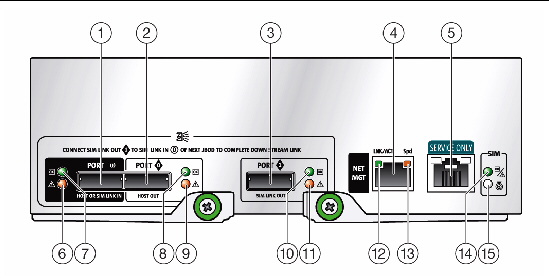
FIGURE 1 illustrates the location of the SIM board components and LEDs.
FIGURE 1 SIM Board Components and LEDs

|
Network management port speed LED (amber on indicates 100 megabits per second; amber off indicates 10 megabits per second) |
|
To replace a failed SIM board, you must complete the following steps, which are explained in detail in the remainder of this guide:
1. Remove the failed SIM board. See To Remove the Failed SIM Board.
2. Install the replacement SIM board. See To Install the New SIM Board.
3. Verify the installation. See To Verify the SIM Board Replacement.

|
Caution - Potential loss of data access.If any of the port LEDs on the SIM board (FIGURE 1) are blinking, there is data actively moving in and out of the disk shelf. If you remove the SIM, data might be lost. |
| Note - The SIM boards are hot-swappable. You do not need to disconnect power from the system or other components in order to replace one of these components. |
|
1. From the back of the chassis, locate the failed SIM.
2. Label each mini-SAS cable connection for reconnection to the same connectors on the replacement chassis.
For example, Disk Shelf 1, SIM Link Out to Disk Shelf 0, Host or SIM Link In.
3. Disconnect the labeled mini-SAS cables from each SIM board:
a. Grasp the metal body of the connector with one hand, and use your other hand to firmly grasp and pull the tab.
b. Pull the tab gently toward the connector body, and then with your other hand, extract the connector from the chassis.
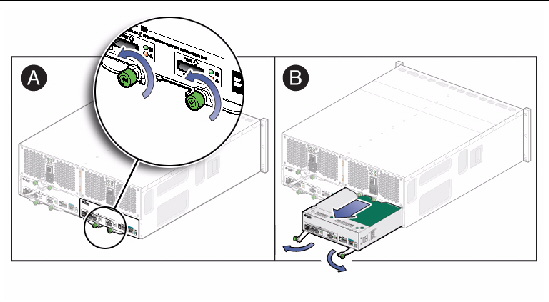
4. Remove the SIM board from the chassis (FIGURE 2):
a. Loosen the two captive screws on the ejection levers and pull the ejection levers fully out to partially eject the SIM board from the chassis.
If the captive screws are too tight to loosen by hand, use a Phillips No. 2 screwdriver to loosen each screw.
b. Pull the SIM board from the chassis.
5. Place the SIM board aside on an antistatic surface or in antistatic packaging.


|
Caution - Use care when handling either the new or failed SIM board. Ensure that all ESD precautions are being followed. |
|
2. Place the failed SIM board in the packing materials so that you can return it to Oracle for proper disposal.
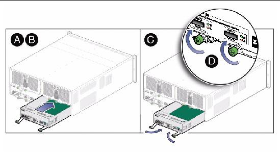
3. Insert the new SIM board into the back of the chassis (FIGURE 3):
a. Swing both SIM board ejection levers to the fully open position.
b. Align the SIM board with the open slot and slide it into the chassis until it engages with the chassis connectors and the ejection levers begin to swing closed.
| Note - If the SIM board does not fit into the slot, check that you have the correct SIM board for this system. |
c. Simultaneously push both ejection levers toward the middle of the board to seat it in the chassis.
d. Tighten the two ejection lever captive screws to secure the board.
FIGURE 3 Installing a SIM Board

4. Reconnect the mini-SAS cables to their original locations.
|
 Wait approximately 60 seconds for the SIM board to complete its boot process, at which point ensure that the SIM board OK LED is lit green.
These web sites provide additional resources:
Submit comments about this document at:
http://www.oracle.com/goto/docfeedback
Include the title and part number of your document with your feedback:
Sun Disk Shelf-24x3.5" SAS-2,
part number 820-7244-12

Copyright © 2012, Oracle and/or its affiliates. All rights reserved.