Diagnosing Faults With LEDs and Indicators
This section describes how to use the storage module LEDs and indicators to
isolate faults with components.
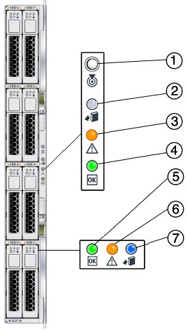
Front Panel Indicators and Buttons
The front panel provides visual status to the disk drives and the
storage module.

|
|
|
|---|
1 |
Combined Locate button and LED (white) |
This LED helps identify which
module you are working on in a chassis full of servers.
Push and release this button to make the Locate LED blink for 30 minutes. When the Locate LED is blinking, push and release this button to make the Locate LED stop blinking. Hold down the button for 5 seconds to initiate a “push-to-test” mode that illuminates all other LEDs for 15 seconds. This LED can also be made to blink from a remote system using the CMM ILOM. Refer to the Sun Blade Storage Module M2 Administration Guide for details.
|
2 |
Indicator not applicable |
- This LED is not used on this product.
|
3 |
|
|
4 |
|
This LED has three
states:
On: Module is configured and online. Off: Module is not configured or is offline. Blinking: Module is configuring or a firmware flash update is in progress.
|
5 |
Disk Drive Activity LED (green) |
This LED has three states:
On: Power is on and disk is online. Off: Disk is offline. Blinking: Irregular blinking means normal disk activity; steady, slow blink means RAID activity (such as a rebuild).
|
6 |
Disk Drive Fault and
Locate LED (amber) |
This LED has four states:
On: Disk fault. Service action required. Off: Normal operation. Slow blink: Disk failure predicted. Fast blink: Locate function activated.
|
7 |
Disk Drive Ready-to-Remove LED (blue) |
This LED
has two states:
On: Ready to remove. Off: Normal operation.
|
|

