Introduction to the Sun Fire X4500 and X4540 Servers
|
This chapter contains an overview of the Sun Fire X4500 and X4540 servers, including features and orderable components.
This chapter contains the following procedures and information:
1.1 Features of the Sun Fire X4500
The Sun Fire X4500 server is a mid-level, modular, rack-optimized server in the Sun x64 product family; the family platform includes servers engineered for AMD Opteron CPUs and deployment into commercial server markets in a slide-mounted, horizontally biased enclosure for rack cabinet installations, primarily in datacenter locations.
1.1.1 System Configurations (X4500)
The server provides the following maximum system configurations:
- 8 DDR-I DIMM slots (4 per processor), up to 2 GB per DIMM (16 GB per system)
- Up to forty-eight 3.5-inch SATA-I disk drives of 250 to 1 TB capacity each (48 TB total system capacity)
- Two 133-MHz PCI-X slots
1.1.2 Standard I/O (X4500)
The standard I/O for the Sun Fire X4500 is:
- Four 10/100/1000 BASE-T Gigabit Ethernet ports
- VGA video port
- Serial management port
- Four USB ports
- One 10/100BASE-T Ethernet management port
The Sun Fire X4500 server includes an extensive set of reliability, availability, and serviceability (RAS) features, such as:
- Hot-pluggable and redundant disk drives
- Hot-swappable fans
- Hot-swappable power supplies
The servers also provide an Integrated Lights Out Management (ILOM) service processor function that includes remote boot and remote software upgrades.
1.1.3 Summary of Features (X4500)
TABLE 1-1 summarizes the features of the Sun Fire X4500 server.
TABLE 1-1 Summary of Features (X4500)
|
Feature or Component
|
Sun Fire X4500 Server
|
|
CPU
|
Two Revision E AMD64 Opteron quad-core processors on two CPU modules.
|
|
Processor BIOS
|
8 Mbit Flash memory with LPC interface.
|
|
Memory
|
8 DDR-I DIMM slots (4 per processor), up to 2 GB per DIMM (16 GB per system).
|
|
Disk drives
|
Up to forty-eight 3.5-inch SATAType-1 disk drives of 250 to 1 TB capacity each (48 TB total system capacity).
|
|
Service Processor
|
SP card mounted on video card in PCI slot that runs Integrated Lights Out Manager (ILOM) as described in the ILOM documentation (see Related Documentation).
|
|
Network I/O
|
- Four 10/100/1000BASE-T Gigabit Ethernet ports (RJ-45 connectors)
- One 10/100BASE-T Ethernet net management port (RJ-45 Connector)
- One RS-232 serial port (RJ-45 Connector)
|
|
PCI I/O
|
Two available PCI-X slots (x8), LSI SAS 1068E. (Third slot is reserved for a video card that system boots off until host software boots.)
- Six SATA Controllers on IO Board, LSI SATA controller x 6. Each
controller supports 8 drives
- 51.5 mm (2.5 inches) maximum height
- 169.3 mm (6.7 inches) maximum length
|
|
Other I/O
|
- Four USB 2.0 ports
- One VGA video port (D-15 connector)
|
|
Power
|
1500 W DC max output per power supply, two bays, 1+1 redundancy, hot-swappable.
1130 W AC max system input power = 3856 BTU/hr = 0.321 Tons of Air Conditioning, 200-240 VAC.
|
|
Fans
|
Five fan modules; also additional fans in each power supply.
Cooling is front-to-back forced air.
|
1.2 Features of the Sun Fire X4540
The Sun Fire X4540 server is a mid-level, modular, rack-optimized server in the Sun x64 product family; the family platform includes servers engineered for AMD Opteron CPUs and deployment into commercial server markets in a slide-mounted, horizontally biased enclosure for rack cabinet installations, primarily in datacenter locations.
1.2.1 System Configurations (X4540)
The server provides the following maximum system configurations:
- 16 DDR-II DIMM slots (8 per processor) 64GB maximum with 2 CPUs and 4 GB DIMMs, standard 32GB
- Up to forty-eight 3.5-inch SATA-II disk drives of 250 - 1TB capacity (48 TB total system capacity)
- Three x8 PCIe slots
- Supports solid-state drives
1.2.2 Standard I/O (X4540)
- Four 10/100/1000 BASE-T Gigabit Ethernet ports
- Three PCIe ports
- VGA video port
- Four USB 2.0 ports (2 front, 2 rear)
- One 10/100BASE-T Ethernet management port
- Compact Flash slot
- Serial management port (R45, no LEDs)
The Sun Fire X4540 server includes an extensive set of reliability, availability, and serviceability (RAS) features, such as:
- Hot-pluggable and redundant disk drives and SSDs
- Hot-swappable fans
- Hot-swappable power supplies
- Hot-swappable SATA disk drives
The servers also provide an Integrated Lights-Out Management (ILOM) service processor function that includes remote boot and remote software upgrades.
1.2.3 Summary of Features (X4540)
TABLE 1-2 summarizes the features of the Sun Fire X4540 server.
TABLE 1-2 Summary of Features (X4540)
|
Feature or Component
|
Sun Fire X4540 Server
|
|
CPU
|
Two 2000 Series quad-core AMD Opteron Processor, 2-socket configuration.
Two 8000/2000 Series six-core AMD Opteron Processor
|
|
Processor BIOS
|
STMicro 8 Mbit Flash memory with LPC interface.
|
|
Memory
|
16 DDR-II DIMM slots (8 per processor), up to 4 GB per DIMM (64 GB per system).
|
|
Disk drives
|
Up to 48 250MB to 1 TB capacity, 3.5-inch SATA Type-I and II drives (48 TB total system capacity).
One to eight 3.5” SATA SSDs.
|
|
Solid-state drives (SSD)
|
One to eight 32-GB, 3.5-inch, SATA SSDs can be installed into the system.
|
|
Service Processor
|
SP circuitry running Integrated Lights Out Manager (ILOM) as described in the ILOM documentation (see Related Documentation).
|
|
Network I/O
|
- Four 10/100/1000BASE-T Ethernet ports (RJ-45 connectors)
- One 10/100BASE-T Ethernet net management port (RJ-45 Connector)
- One RS-232 serial port (RJ-45 Connector)
- Four (4) USB 2.0 Ports (Type A Connector) (2x in front and 2x in rear)
- Video Port (D-15 VGA Connector)
- CF Type-I or Type-II slot
|
|
Serial port
|
- RS-232 serial interface (RJ45 connector, no LEDs)
- Console only, no modem support (no RI, PPP)
- Connected to ILOM by default
- Default parameters
9600 baud
8 data bits
No parity
1 stop bit
No flow control
|
|
PCIe I/O
|
Three low-profile x8 PCIe slots.
|
|
Other I/O
|
- Four USB 2.0 ports
- One VGA video port (D-15 connector on controller)
- Compact Flash card slot
|
|
Power
|
- 1500 W DC max output per power supply, two bays, 1+1 redundancy, hot-swappable.
- 1000 Watts max input power (3412 BTU/h =Maximum air flow is 200 CFM maximum air flow.
- 5 Amps max operating current @ 220 VAC (198 VAC to 264 VAC range), 50 to 60 Hz.
|
|
Fans
|
- Five fan modules; also additional fans in each power supply.
- Cooling is front-to-back forced air. Hot swappable, Variable speed,
- 7500 R.P.M. max, Top loading, Fault/OK LEDs,1.8A/18W, SATAconnector.
- The SP software controls the fan speed and detects fan failure. Operation terminates if a fan tray is removed.
Note - Do not operate the system with a fan removed for more than 60 seconds
|
1.3 Exterior Features, Controls, and Indicators
This section shows, lists, and describes the features and the controls and indicators on the front and rear panels of the Sun Fire X4500/X4540 server.
| Note - For a quick and concise description of these features refer to the service label located on the hard drive access cover.
|
This section contains the following procedures and information:
1.3.1 Front Panel
FIGURE 1-1 shows the front panel.
FIGURE 1-1 Sun Fire X4500/X4540 Server Front Panel Features

Figure Legend
|
1
|
Serial number label
|
|
2
|
Two USB 2.0 connectors
|
|
3
|
Serial number label
|
1.3.2 Front Panel Controls and Indicators
FIGURE 1-2 shows a close up of the controls and indicators.
For more on LED behavior, see Status Indicator LEDs.
FIGURE 1-2 Controls and Indicators

Figure Legend
|
1
|
Locate button/LED
|
|
2
|
System Fault LED
|
|
3
|
Power/OK LED
|
|
4
|
System power button
|
|
5
|
Top fault LED
|
|
6
|
Rear fault LED
|
|
7
|
System Over Temperature
|
1.3.3 Rear Panel (X4500)
FIGURE 1-3 shows the features of the rear panel. TABLE 1-3 lists and describes each feature.
FIGURE 1-3 Sun Fire X4500 Rear Panel

TABLE 1-3 Figure Legend--Sun Fire X4500 Rear Panel Features
|
#
|
Name
|
Description
|
|
1
|
Power Supply LED
(amber)
|
Steady on--Fault. Service action required.
Off--No fault.
|
|
2
|
Power Supply LED (green)
|
Steady on--Power is on (AC/DC are OK).
Blinking --Blinks briefly once every 3 seconds. Standby power is on (AC is OK).
Off -- Power is off.
|
|
3
|
AC power connector
|
Each power supply has its own AC connector with a
clip to secure its power cable.
|
|
4
|
Chassis ground
|
To connect grounding straps
|
|
5
|
Mounting plate for (Cable Management Assembly) CMA bracket
|
To secure the CMA, as described in the Sun X4500-J Slide Rail Installation Guide or the Sun Fire X4500 Server Getting Started Guide.
|
|
6
|
PCI-X-0 and PCI-X-1
|
Two slots for PCI-X cards.
|
|
7
|
Network management port
|
NET MGT -- Net management and service processor 10/100 Mbit/sec Ethernet port.
|
|
8
|
Video connector
|
VGA port to connect video monitor.
|
|
9
|
Serial management port
|
SER MGT--RJ45 serial management port (serial connection to service processor).
|
|
10
|
Locate button/LED (white)
|
Toggles on/off locally--Operators can turn on this on remotely to help them locate the enclosure in a crowded server room. Press to turn off.
|
|
11
|
System Fault LED (amber)
|
Off--Normal operation
On--Service action is required.
A system running under these conditions are in a fault condition, but the SP does not log the reason the service LED is illuminated:
- 220VAC with only 1 PSU
- 110VAC with only two PSUs
|
|
12
|
System Status LED (green)
|
Steady on-- Power is on and system is operational.
Blinking--Standby power is on but main power is off. Blinks briefly once every 3 seconds.
Off -- Power is off.
|
|
13
|
USB ports
|
To connect USB 2.0 devices.
|
|
14
|
10/100/1000 Gigabit Ethernet ports
|
To connect server to Ethernet.
|
|
15
|
System Controller status
LEDs
|
Blue -- Ready to remove (service action allowed)
Amber -- Fault (Service action required)
Green -- OK (no action required)
|
|
16
|
Reset buttons
|
Caution - Do not use these buttons unless instructed to do so by Sun service personnel. To operate these buttons, insert a nonconducting stylus into the recess.
- SP -- Service Processor.
- HOST - This button resets the CPU but not the service processor.
|
1.3.4 Rear Panel (X4540)
| Note - For a quick and concise description of these actions refer to the service label located on the hard drive access cover.
|
FIGURE 1-4 shows the features of the rear panel. TABLE 1-4 lists and describes each feature.
FIGURE 1-4 Sun Fire X4540 Server Rear Panel

TABLE 1-4 Sun Fire X4540 Rear Panel Features
|
#
|
Name
|
Description
|
|
1
|
Power Supply Fault LED
(amber)
|
When on, service action is required.
|
|
2
|
Power Supply LED (green)
|
Steady on--Power is on (AC/DC are OK).
Blinking--Standby power is on (AC is OK). Blinks briefly every 3 seconds.
Off--Power is off.
|
|
3
|
AC power connectors
|
Each power supply has its own AC connector with a clip to secure its power cable.
|
|
4
|
Chassis ground
|
To connect grounding straps.
|
|
5
|
Mounting plate
|
Only for mounting CMA on X4500.
|
|
6
|
PCIe
|
Three slots for X-option cards.
|
|
7
|
Locate button/LED (white)
|
Toggles on/off locally--Operators can turn on this LED remotely to help them locate the server in a crowded server room. Press to turn off.
|
|
8
|
Fault LED
|
Amber--When on, service action is required.
Off--No faults present.
|
|
9
|
Enclosure OK LED (green)
|
Steady on-- Power is on and system is operational.
Blinking--Standby power is on but main power is off. Blinks briefly once every 3 seconds.
Off -- Power is off.
|
|
10
|
Reset buttons
|
Caution - Do not use these buttons unless instructed to do so by Sun service personnel. To operate these buttons, insert a nonconducting stylus or a straightened paper clip into the recess.
- SP -- Service Processor.
- NMI - Non-Maskable Interrupt dump. This button sends an NMI to the CPU. It is used for debugging purposes only. (Supported on Windows platforms only.)
- HOST - This button resets the CPU but not the service processor.
|
|
11
|
System controller status LEDs
|
Blue - Ready to remove (service action allowed).
Amber - Fault (service action required).
Green - Operational (no action required).
|
|
12
|
Serial management port
|
SER MGT--Serial management port (serial connection to service processor).
|
|
13
|
Network management port
|
NET MGT -- Net management and service processor 10/100 Mbit/sec Ethernet port.
|
|
14
|
10/100/1000 Gigabit Ethernet ports
|
To connect server to Ethernet.
|
|
15
|
USB connectors
|
To connect USB 2.0 devices.
|
|
16
|
Video connector
|
VGA port to connect video monitor.
|
|
17
|
Compact Flash (CF) card
|
Slot to insert Compact Flash card. Push once and button comes out. Push second time and card ejects.
|
FIGURE 1-5 shows the locations of the Sun Fire X4540 server components, with the covers removed.
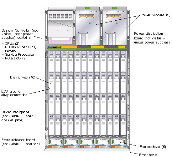
1.3.5 Component Locations (X4500)
FIGURE 1-5 Sun Fire X4500 Component Locations

1.3.6 Component Locations (X4540)
FIGURE 1-6 Sun Fire X4540 Component Locations
 [ D ]
[ D ]
1.3.7 Sensor Information
Information on the location of the server’s sensors can be found in Sun Fire X4500/X4540 Servers Diagnostics Guide, 819-4363.
For information on sensors that report on hardware conditions, see Sun Integrated Lights Out Manager 3.0 Supplement for Sun Fire X4540 Server, 820-5549-10.
1.4 Accessory Kit (X4500)
TABLE 1-5 lists the contents of the accessory kit that is shipped with the Sun Fire X4500 server.
| Note - Because of Sun’s commitment to eco-responsibility, we are not shipping a printed installation guide and software CDs for the new Sun Fire X4540 Server. Customers can order the documentation and CDs through the SunStore or Sun sales support representative. The Installation Guide and software are also available on the Web at no charge.
|
TABLE 1-5 Sun Fire X4500 Accessory Kit
|
Item
|
|
Bootable Diagnostics CD
|
|
Sun Fire X4500 Where To Find (printed manual)
|
|
Serial-to-RJ45 cable adapter (DB9S-to-RJ-45F)
|
|
Sun Fire X4500 Installation Guide (printed manual)
|
|
Sun Fire X4500 Tools and Drivers CD
|
|
Sun Installation Assistant CD
|
|
Important Safety Information for Sun Hardware Systems (printed manual)
|
|
Software License Agreement (printed manual)
|
1.5 Accessory Kit (X4540)
TABLE 1-6 lists the contents of the accessory kit that is shipped with the Sun Fire X4540 server.
TABLE 1-6 Sun Fire X4540 Accessory Kit
|
Item
|
|
Sun Fire X4540 Getting Started Guide (printed manual)
|
|
Serial-to-RJ45 cable adapter (DB9S-to-RJ-45F)
|
|
Important Safety Information for Sun Hardware Systems (printed manual)
|
|
Software License Agreement (printed manual)
|
1.6 Additional Options and Replaceable Components (X4500)
TABLE 1-7 lists the after-factory options and replaceable components for the Sun Fire X4500 server. Whether the items are customer-replaceable units (CRUs) or field-replaceable units (FRUs) is indicated in the last column of the table.
Supported components and their part numbers are subject to change over time. For the most up-to-date list of replaceable components, product updates, and downloads, see the following URL:
http://sunsolve.sun.com/handbook_pub/Systems/
TABLE 1-7 Sun Fire X4500 Replaceable Components
|
Component
|
Part Number
|
CRU or FRU
|
|
Power Supply
|
#300-1787,
X4502A-Z (X-option)
|
CRU
|
|
Fan Module (5 Fan Modules/system)
|
#541-0458
|
CRU
|
|
Seagate Galaxy 250GB
|
#541-1468
|
CRU
|
|
Hitachi Kurafone2 500GB
|
#541-1467
|
CRU
|
|
Hitachi GeminiK 500GB
|
#541-3050
|
CRU
|
|
Hitachi GeminiK 750GB
|
#540-7244
|
CRU
|
|
Hitachi GeminiK 1TB
|
#540-7507
|
CRU
|
|
2-GB DIMMs, Pair (2 DIMMs, 4 GB total) Registered ECC Memory, 8 slots/system
|
#541-1903
X4231A-Z (X-option)
|
CRU
|
|
GRASP board (includes SP board and video board)
|
#541-2963
|
FRU
|
|
CPU (AMD 290, 2.8-GHz dual core), includes grease
|
#371-1779
|
FRU
|
|
System Controller Assembly (with I/O controller board and CPU board; without CPUs, DIMMs, and GRASP board.)
|
#541-1915
|
FRU
|
|
Front Indicator Board (FIB) with ribbon cable
|
#501-7192
|
FRU
|
|
System Enclosure Super FRU (includes disk backplane and FIB with ribbon cable)
|
#541-1907
|
FRU
|
|
Power Distribution Board (220 VAC)
|
#501-7104
|
FRU
|
|
Battery
|
#150-3993
|
CRU
|
|
Rack Mount X-Options
|
|
|
|
Cable Management Arm
|
#371-2887,
X4229A-Z (X-option)
|
FRU
|
|
Slide Rail Kit (JES)
|
#371-3493,
X4228A-Z (X-option)
|
FRU
|
1.7 Additional Options and Replaceable Components (X4540)
TABLE 1-8 lists the after-factory options and replaceable components for the Sun Fire X4540 server. Whether the items are customer-replaceable units (CRUs) or field-replaceable units (FRUs) is indicated in the last column of the table.
Supported components and their part numbers are subject to change over time. For the most up-to-date list of replaceable components, product updates, and downloads, see the following URL:
http://sunsolve.sun.com/handbook_pub/Systems/
Click the name and model of your server, and then click the Full Components List for the list of components and part numbers.
TABLE 1-8 Sun Fire X4540 Replaceable Components
|
Component
|
Marketing Part Number
|
CRU or FRU
|
|
Power supply (type A205), 1500W (X4500, 2 or 3 per system)
|
#300-1787,
X4502A-Z (X-option)
|
CRU
|
|
Fan Module (5 Fan Modules/system)
|
#341-0458
|
CRU
|
|
Seagate 250GB
|
#541-3678, XRA-ST1CH-250G7KZ (X-option)
|
CRU
|
|
Hitachi 500GB
|
#541-3050, XRA-ST1CH-500G7KZ (X-option)
|
CRU
|
|
Hitachi 1TB
|
#540-7507, XRA-ST1CH-1T7K (X-option)
|
CRU
|
|
Seagate 500GB
|
#541-3679
|
CRU
|
|
Seagate 1TB
|
#541-3730
|
CRU
|
|
32GB 3.5" SATA SSD
|
#541-4077, XRA-ST1CH-32G2SSD (X-option)
|
CRU
|
|
2 DIMMs x 2GB, 512Mb-based, dual-rank DIMMs
(4 GB total) registered ECC Memory, 16 slots/system
|
#541-1313
X5034 (X-option)
|
CRU
|
|
2 DIMMs x 2GB, 1Gb-based, single-rank DIMMs
(8 GB total) registered ECC Memory, 16 slots/system
|
#541-3360
X4540 (X-option)
|
CRU
|
|
2 DIMMs x 4GB, 1Gb-based, single-rank DIMMs
(8 GB total) registered ECC Memory, 16 slots/system
|
#541-1304
X5035 (X-option)
|
CRU
|
|
2 DIMMs x 8GB, 2Gb-based, single-rank DIMMs
(8 GB total) registered ECC Memory, 16 slots/system
|
#541-3419
X8356A (X-option)
|
CRU
|
|
System Controller Assembly with I/O controller board and CPU board; without CPUs, DIMMs, and GRASP board. (Only compatible with quad-core 2356 processor.)
|
#541-0491
|
FRU
|
|
System Controller Assembly with I/O controller board and CPU board; without CPUs, DIMMs, and GRASP board. (Compatible with quad-core 2356 or 2384 processor.)
|
#541-3758
|
FRU
|
|
Graphics Service Processor (GRASP) board, includes SP board and video board
|
#541-0597
|
FRU
|
|
CPU (quad core 2.3 GHz 2356 processor)
|
#371-4042
|
FRU
|
|
CPU (quad core 2.7 GHz 2384 processor)
|
#371-4438
|
FRU
|
|
Front Indicator Board (FIB) with ribbon cable
|
#501-7192
|
FRU
|
|
System Enclosure Super FRU with disk backplane and FIB with ribbon cable
|
#541-1218
|
FRU
|
|
System Controller Upgrade Kit (includes I/O controller board (USB) and CPU board, 2x2356, 16x2GB (1GB), and document)
|
B24-FSZ2-4540-CONT (X-option)
|
CRU
|
|
System Controller Upgrade Kit (includes I/O controller board (USB) and CPU board, 2x2435, 16x2GB (1GB), and document)
|
B24-BZ2-4540-CONT (X-option)
|
CRU
|
|
Power Distribution Board (220 VAC)
|
#501-7104
|
FRU
|
|
Battery
|
#150-3993
|
CRU
|
|
Rack Mount X-Options
|
|
|
|
Slide Rail Kit
|
#350-1393,
X4541 (X-option)
|
FRU
|
|
Cable Management Arm (compatible only with Slide Rail Kit #371-3493)
|
#371-2887,
X4229A-Z (X-option)
|
FRU
|
|
New Cable Management Arm with Cable Management Bar (compatible only with Slide Rail Kit #350-1393)
|
#350-1363,
X4542 (X-option)
|
FRU
|
| Sun Fire X4500/X4540 Server Service Manual
|
819-4359-19
|
   
|
Copyright © 2010, Oracle and/or its affiliates. All rights reserved.