|
Sun Fire X4540 Server ILOM 3.0 Supplement |
The Sun Fire X4540 server runs ILOM 3.0. However, some ILOM features that are not applicable to these servers are not implemented. Other features are implemented in a platform-specific way.
This supplement describes the differences between the ILOM 3.0 platform-specific user interface provided on the Sun Fire X4540 server and the user interface provided by ILOM 3.0. For a description of all the features and capabilities offered by the ILOM 3.0 firmware, see the Sun Integrated Lights Out Manager 3.0 User’s Guide (820-4597).
The following topics are covered in this supplement:
With the exception of Power Policy Configuration, all ILOM 3.0 firmware features are supported on the Sun Fire X4540 server.
For a complete list of ILOM 3.0 firmware features, see the Sun Integrated Lights Out Manager 3.0 User’s Guide (820-4597).
TABLE 1 lists the differences between the ILOM 3.0 web interface and the ILOM 3.0 platform-specific web interface on the Sun Fire X4540 server.
The Keyboard Controller Style (KCS) interface enables you to use the host operating system to execute ipmitool commands on the ILOM service processor (SP). Using ipmitool commands you can perform server, initialization, monitoring, and maintenance tasks from the host operating system.
| Note - The KCS interface is sometimes to referred to as the Baseboard Management Controller (BMC) interface. |
The Sun Fire X44540 server supports in-band systems management using IPMI v1.5 or 2.0 with the KCS interface and the IPMI kernel driver. IPMI is an industry-supported standard for performing autonomous platform management functions.
You can run ipmitool commands on Solaris, Linux, and Windows Server 2003 R2 Enterprise operating systems. For a description of the ipmitool commands and options, see the ipmitool manpage on the web at:
http://ipmitool.sourceforge.net/manpage.html
The following are a few ipmitool commands for the operating systems supported by the server.
# ipmitool -I interface sdr list
# ipmitool -I interface sel list
# ipmitool -I interface lan print 1
Where interface is bmc on Solaris systems and open on Linux systems.
If you are using a Solaris or Linux operating system, refer to Remote Monitoring of Sun X64 Systems Using IPMITOOL and IPMIEVD (820-1011) for ipmitool installation and user instructions. This document is available on the web at:
http://www.sun.com/blueprints/0107/820-1011.pdf
If you are using a Windows Server 2003 R2 operating system, install the optional Windows Hardware Management interface driver. For instructions on how to install this driver, refer to Hardware Management in Microsoft Windows Server 2003 R2 RC0 and perform the procedure “How to Enable the Hardware Management Feature.” It is not necessary to perform any of the other procedures described this document, such as “Configuration and Security.” This document is available on the web at:
http://www.microsoft.com/technet/scriptcenter/preview/wsm/enable.mspx#ECB
Additional information on IPMI, including the ipmitool manpage and detailed specifications, is available on the web at the following locations:
http://ipmitool.sourceforge.net/manpage.html
http://openipmi.sourceforge.net
http://www.intel.com/design/servers/ipmi/spec.htm
The Sun Fire X4540 server supports the power monitoring commands provided by the ILOM 3.0 Power Consumption Management interfaces. You can monitor power using the web interface and the command-line interface (CLI).
The following power properties are supported:
To monitor power using the web interface, open a browser, log in to the web interface, and select the System Monitoring->Power Management tab.
To monitor power using the CLI, log in to the CLI and type this command:
For more information on power consumption management, see the Sun Integrated Lights Out Manager 3.0 User’s Guide (820-4597).
The ILOM firmware upgrade process does the following:
In order to update the BIOS image, the operating system running on the server must be shut down. Because it may be inconvenient or time consuming to shut down the operating system and the server when you complete the firmware upgrade, a new option has been added to the platform-specific ILOM 3.0 that runs on the on the Sun Fire X4540 server. This option enables you to delay the upgrade to the BIOS image to the next time the server is reset (shutdown and restarted).
The firmware upgrade procedure consists of the following steps:
1. Checking the version of ILOM running on the server.
You should check the version of ILOM running on the server before you download the ILOM firmware to ensure that a newer version of the firmware is available for downloading.
2. Downloading the ILOM firmware.
3. Upgrading the ILOM firmware.
Refer to the following sections for detailed instructions:
|
1. Log in to any user account that is assigned the Admin (a) role.
2. To check the firmware version, type version.
The current firmware version information appears.
|
1. Log in to any user account that is assigned the Admin (a) role.
2. Select System Information ->Version.
The Versions page appears displaying the current firmware version information.
|
1. Browse to http://www.sun.com/download/
The Sun Download page appears.
2. Select the View by Category tab, scroll down the Hardware Drivers section, and click on X64 Servers and Workstations.
The Sun Downloads x64 Servers & Workstations page appears.
3. Locate the Sun Fire X4540 server in the left column of the product list and click Download.
The Sun Fire X4540 Server page appears.
4. In the right column of the table, click Download.
The Sun Fire X4540 information page appears.
5. In the Platform drop-down list, select Firmware.
6. In the Language drop-down list, select the desired language.
7. Select the I agree to the Software License Agreement check box to accept the license agreement.
8. Enter your user name and password and click Login and Continue.
The Download Sun Fire X4540 3.0 for Firmware, English page appears.
| Note - If you do not have a user name and password, you can register free of charge by clicking Register Now. |
9. Follow the on-screen instructions to download the ILOM and BIOS binary. The download file name is similar to this: ilom.x4540-3.0.1.1_35519e.ima.
|
1. Log in to any user account that is assigned the Admin (a) role.
2. Type the following command to upgrade ILOM firmware image:
->load -source tftp://ipaddress/firmwaredirectory/filename.ima
3. Type y to proceed with the upgrade.
4. If you want to preserve the configuration, type y; otherwise type n.
5. If you want to delay the BIOS firmware upgrade and not force a server shutdown, type n; otherwise type y.
| Note - If you type n, the server will not be forced to shut down and the BIOS firmware will be upgraded the next time the server shuts down and restarts. |
The upgrade process begins and the following information is displayed when the upgrade is complete.
6. The ILOM 3.0 firmware upgrade is now complete.
|
1. Log in to any user account that is assigned the Admin (a) role.
2. Select Maintenance --> Firmware Upgrade.
The Firmware Upgrade page appears (see FIGURE 1).
FIGURE 1 Firmware Upgrade Page

The Firmware Upgrade - Upload page appears. This page provides the Specify URL field for specifying the location of the firmware package (see FIGURE 2).
FIGURE 2 Firmware Upgrade - Upload Page
4. To specify the location of the firmware package file, do one of the following:
a. Click Specify URL and enter the URL for the firmware package file.
b. Click Browse and browse to the location of the firmware package file.
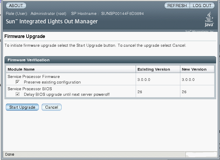
The Firmware Upgrade - Start Upgrade page appears (see FIGURE 3).
FIGURE 3 Firmware Upgrade - Start Upgrade Page

6. If you want to preserve the existing server configuration, select the Preserve existing configuration check box.
7. If you want to delay the BIOS upgrade until the next time the server powers off and reboots, select the Delay BIOS upgrade until next server poweroff check box.
8. Click the Start Upgrade button to upgrade the firmware.
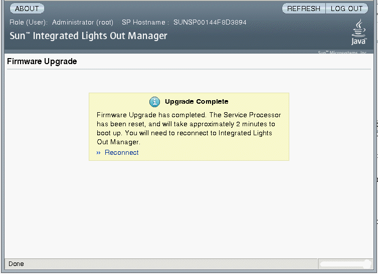
When you click the Start Upgrade button, a progress screen appears and indicates that the firmware is being updated. Once the update progress reaches 100%, the Upgrade Complete page appears (see FIGURE 4) and the SP automatically reboots.
FIGURE 4 Firmware Upgrade - Upgrade Complete Page

9. After the SP finishes rebooting, use your browser to reconnect to ILOM.
In ILOM 3.0, the root account--which was used for administrative tasks in ILOM 2.0--has been removed and the default user account is used for initial login, creation of user accounts, and server configuration. After those tasks are performed, the default user account’s access is limited to the CLI on the SP console. Therefore, all subsequent user account changes (creations and modifications) and configuration changes should be done using specific user accounts. This requirement enables accountability to be traced to individual users who have access to specific accounts.
As mentioned, once you login to the default user account, subsequent access to this account is restricted to the CLI on the SP console, which connects through the serial management port. Additionally, by default, the SP requires that a “physical presence” switch be pressed on the server before the SP console can be used for this purpose. This requirement is there for security reasons as it prevents access to the default user account from a remote location, that is, you must have physical access to the server to use this account.
One of the uses of the default user account is lost password recovery. It is meant to be used when you cannot access the account for which the password was lost by using a different user account. User accounts assigned the user (u) role can be used to change and reset passwords on other user accounts. If there are no user accounts that have the ability to reset passwords, you can use the CLI on the SP console to log in to the default user account.
|
1. Connect a serial cable from the RJ-45 SER MGT port on the server’s back panel to a terminal device.
For instructions, refer to the Sun Fire X4500 and X4540 Servers Installation Guide (820-2394).
2. Ensure that the server is powered on.
The localhost login prompt appears.
3. Log in to the default user account. Type:
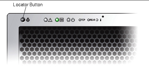
4. Press the Locator button once.
This Locator button is on the front of the server (see FIGURE 5).
FIGURE 5 Sun Fire X4540 Locator Button

5. Press the Enter key on the terminal device.
The SP displays the Password prompt.
6. Enter the password for the default user account.
The default user account password is the product serial number and it cannot be changed. The product serial number is printed on the server hardware or on the product purchase documentation.
Once you have successfully logged in, the SP displays its default CLI command prompt: ->
7. You can now use the default user account to reset the passwords for user accounts for which passwords have been lost.
For instructions on how to use the CLI to reset user passwords, see the Sun Integrated Lights Out Manager 3.0 User’s Guide (820-4597).
The server includes a number of sensors that report on hardware conditions. Many of the sensor readings are used to adjust the fan speeds and perform other actions, such as illuminating LEDs and powering off the server.
This sections describes the sensors that ILOM monitors for the Sun Fire X4540 server.
The following types of sensors are described:
| Note - To view disk information, use the ipmitool sdr data command. The ILOM 3.x Sensor Readings GUI screen does not provide drive information. |
TABLE 2 describes the power supply sensors. In the table, n designates the numbers 0-n.
TABLE 3 describes the temperature sensors. In the table, n designates the numbers 0 through n.
|
Processor temperature sensor. Sense if the processor has reached the maximum safe operating temperature. |
TABLE 4 describes the voltage sensors. In the table, n designates the numbers 0-n.
TABLE 5 describes the fan sensor. In the table, n designates the numbers 0-n.
TABLE 6 describes the presence sensors. In the table, n designates the numbers 0-n.
Copyright © 2009 Sun Microsystems, Inc. All rights reserved.