| C H A P T E R 2 |
|
Installing and Powering On the Sun Netra X6270 M2 Server Module |
This chapter contains the following topics:
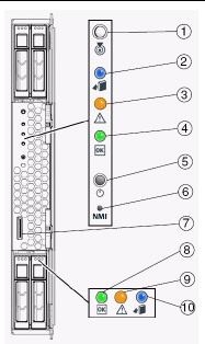
The server module provides standard indicators and buttons, and a Universal Connector Port on its front panel. See FIGURE 2-1 for the locations of LEDs, buttons, and port.

|
Server Module OK/Power LED - Green (blinking or solid state) |
|
Consult the following sections when installing a server module into a powered on chassis:
Prior to installing the server module into a powered-on chassis, ensure that the following requirements are met.
For information about installing chassis components, attaching cables, and powering on the chassis, see the chassis documentation at:
http://docs.sun.com/app/docs/prod/n6000.modsys?l=en&a=view
For instructions, see the Sun Netra X6270 M2 Server Module Service Manual, 821-0939.
|
1. Verify that the chassis is powered-on.
When the chassis is powered-on, the fans are operating and the OK/Power LED illuminates a steady-on green light. The OK/Power LED is located on both the front and rear panels of the chassis. If the chassis is not powered-on, refer to the system chassis documentation.
2. In the front of the chassis, locate and remove the desired server module filler panel.
Pull the lever out and eject the filler panel.
3. Position the server module vertically so that the ejectors are on the right and extend outward.
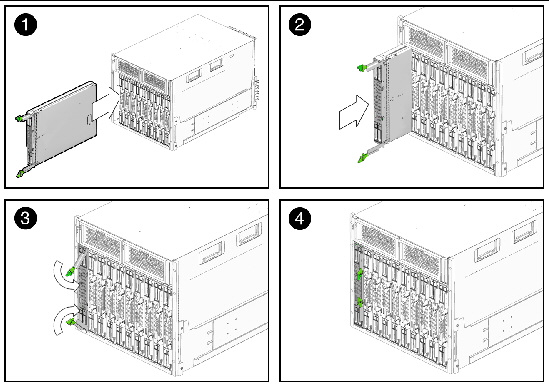
The following illustrations show the server module being inserted into the chassis. See box 1 in FIGURE 2-2.
FIGURE 2-2 Inserting the Server Module Into the Chassis

4. Push the server module into the slot until the server module stops and is flush with the chassis.
See Boxes 2 and 3 in FIGURE 2-2.
5. To lock the server module into the chassis, do the following:
The server module is locked in the chassis (Box 4 in FIGURE 2-2) and Standby power is applied to the server module SP.
After installing a server module into a powered-on chassis, the server module SP automatically boots and standby power from the chassis power supplies is supplied directly to the server module SP. At this time, you can connect to the Oracle Integrated Lights Out Manager (ILOM) and configure an IP address. However, to install an operating system or to fully operate the server module, you must apply main power to the server module host.
For more information about the Sun Netra X6270 M2 server module power states, see the following topics:
|
1. Verify that the system chassis is powered-on.
A steady-on green light should be visible from the chassis OK/Power LED.
If the chassis is not powered on, refer to the system chassis documentation for instructions on powering on the system chassis.
2. Ensure that the OK/Power LED on the server module illuminates a standby blink.
The OK/Power LED on the server module front panel illuminates a standby blink (0.1 second on, 2.9 seconds off). The standby blink indicates that the server module SP is active but the server module host is powered off.
| Note - The server module OK/Power LED will be set to standby blink only when there is enough chassis power for the server module to power on. If there is not enough chassis power, the OK/Power LED will remain off until there is enough power for the server module to power on. To troubleshoot this issue, see Troubleshoot Server Module Power States. |
At this time, standby power is supplied to the server module SP enabling you to connect to the Integrated Lights Out Manager (ILOM) and configure an IP address.
For information about connecting to ILOM and configuring an IP address, see Chapter 2.
|
Main power to the server module host must be applied prior to installing an operating system.
1. Verify that the OK/Power LED on the front panel of the server module is in a standby blink state.
In standby power state, the OK/Power LED on the front panel of the server module illuminates a standby blink (0.1 second on, 2.9 seconds off).
2. Press and release the recessed Power button on the server module front panel.
The OK/Power LED on the server module front panel illuminates a steady-on green light when main power is applied. The steady-on LED state indicates that the server module SP and host are both powered-on.
|
 To power off the server module from main power mode, use one of the following two methods:
This operation will cause any Advanced Configuration and Power Interface (ACPI) enabled operating system to perform an orderly shutdown of the operating system. If the server module is not running ACPI-enabled operating system, the server module will shut down to standby power mode immediately.
|
Each time a server module powers on, it queries the CMM to ensure that there is enough power available from the power supply units (PSUs) to power on the server module. If there is not enough power to power on the server module, the SP denies the server module from receiving power (standby and main). If this situation occurs, the OK/Power LED on the front panel of the server module will remain off. To troubleshoot this power issue, follow these guidelines:
1. Review the ILOM event log messages to determine whether the server module has permission to power on. An event message is recorded in the log any time there is inadequate amount of power available from the PSUs to power on the server module.
For more information about the ILOM event log or monitoring power consumption, refer to the Oracle Integrated Lights Out Manager (ILOM) 3.0 Documentation Collection (see Related Documentation for part numbers).
2. Ensure that the system chassis has the proper amount of power supplies installed to support powering on all the chassis components that are currently installed.
Refer to the system chassis documentation for information about the number of power supplies required to power on chassis components.
3. To avoid power loss, it is recommended that you use the default CMM power management settings in ILOM for power supplies.
For more information about power management, refer to “Power Management Policy” in the Oracle Integrated Lights Out Manager (ILOM) 3.0 Supplement for Sun Netra X6270 M2 Server Module, 821-0943.
| Note - When power-on permissions become available, the OK/Power LED on the front panel of the server module will illuminate a standby blink. |
4. As needed, refer to the Oracle x86 Servers Diagnostics Guide, 820-6750 for instructions on how to run the start-up diagnostic tools provided with the Sun Netra X6270 M2 server module.
Your system chassis is shipped with the following dongle cable that enables you to connect communication devices directly to the Sun Netra X6270 M2 server module:
| Note - The 3-Cable Dongle II is typically provided with each chassis. Additional cables can be ordered. |
You can use the VGA or USB connectors on the dongle cable to communicate with the server module BIOS and operating system. Or, you can use the serial connector to communicate with the server module SP.
|
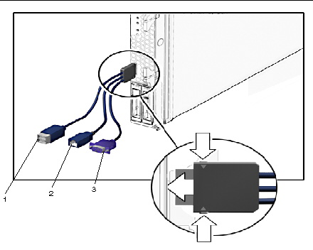
1. Insert the dongle cable into the universal connector port (UCP) on the server module front panel.
See FIGURE 2-3.
2. Attach the connectors on the dongle cable to the appropriate devices.
See FIGURE 2-3.
FIGURE 2-3 Dongle Cable Connections

Copyright © 2010, Oracle and/or its affiliates. All rights reserved.