| Sun Fire X4170, X4270, and X4275 Servers Service Manual |
| C H A P T E R 3 |
|
Servicing Customer-Replaceable Devices |
This chapter describes how to replace the hot-swappable and hot-pluggable customer-replaceable units (CRUs) in the Sun Fire X4170, X4270, and X4275 Servers.
The following topics are covered in this section:
Devices that are hot-pluggable, unlike hot-swappable devices, require actions in addition to physical removal and replacement.
Hot-pluggable devices are those devices that you can remove and install while the server is running. However, you must perform one or more administrative tasks before and/or after installing the hardware (for example, mounting a storage drive).
In the Sun Fire X4170, X4270, and X4275 Servers, storage drives are hot-pluggable. To hot-plug a drive you must take the drive offline (to prevent any applications from accessing it, and to remove the logical software links to it) before you can safely remove it. See Servicing Storage Drives.
Hot-swappable devices are those devices that can be removed and installed while the server is running without requiring any administrative tasks (for example, fan modules and power supplies).
In the Sun Fire X4170, X4270, and X4275 Servers, the following devices are hot-swappable:
| Note - The chassis-mounted storage drives can be hot-swappable, depending on how they are configured. See Servicing Storage Drives. |
The following topics are covered in this section:
FIGURE 3-1 show the physical drive locations for a Sun Fire X4170 Server with eight 2.5-inch storage drives.
FIGURE 3-1 Sun Fire X4170 Server Front Panel

FIGURE 3-2 shows the physical drive locations for the Sun Fire X4270 Server with 16 2.5-inch storage drives.
FIGURE 3-2 Sun Fire X4270 Server Front Panel

FIGURE 3-3 shows the physical drive locations for the Sun Fire X4275 Server with 12 3.5-inch storage drives.
FIGURE 3-3 Sun Fire X4275 Server Front Panel

FIGURE 3-4 shows the storage drive status LEDs.
FIGURE 3-4 Storage Drive Status LEDs

Storage drives can be hot-plugged or cold-plugged (removed when power is off). Storage drives in the servers might be hot-pluggable, depending on the storage drive configuration.
To hot-plug a drive, you must take the drive offline (to prevent any applications from accessing it, and to remove the logical software links to it) before you can safely remove it.
1. Identify the storage drive you wish to remove.
The amber Service Action Required LED might be lit. For specific drive locations, see Server Storage Drive Locations.
2. Determine if the storage drive can be hot-plugged or cold-plugged.
The following conditions might prevent you from hot-plugging a drive. You must power off the server, if the storage drive:
You must take the drive offline before you can safely remove it. This removes the logical software links to the drive and prevents any applications from accessing it. For information on how to take a storage drive offline, see TABLE 3-2.
You must power off the server before you can safely remove the storage drive. Complete one of the procedures described in Power Off the Server.
4. On the drive you plan to remove, push the storage drive release button to open the latch ([1] FIGURE 3-5).
5. Grasp the latch [2] and pull the drive out of the drive slot [3].

|
Caution - The latch is not an ejector. Do not bend it too far to the right. Doing so can damage the latch. |
FIGURE 3-5 Locating the Storage Drive Release Button and Latch

Installing a storage drive into a server is a two-step process. You must first install a storage drive into the drive slot, and then configure that drive to the server.
1. If necessary, remove the blank panel from the chassis.
2. Determine the drive slot location for the replacement storage drive.
If you removed an existing storage drive from a slot in the server, you must install the replacement drive in the same slot as the drive that was removed. Storage drives are physically addressed according to the slot in which they are installed. See FIGURE 3-1, FIGURE 3-2 and FIGURE 3-3 for storage drive locations.
3. Slide the drive into the drive slot until it is fully seated. (FIGURE 3-6)
FIGURE 3-6 Installing a Storage Drive

4. Close the latch to lock the drive in place.
For configuration information, refer to TABLE 3-3.
Restore power to the server. Complete the procedure described in Powering On the Server.
The following topics are covered in this section:
The fan modules are located under the top cover door. Each fan module contains two fans mounted in an integrated, hot-swappable CRU. The Sun Fire X4170 Server has seven pairs of fan modules that provide N+1 cooling redundancy. The Sun Fire X4270 and X4275 Servers have six pairs of fan modules that provide N+1 cooling redundancy.

|
Caution - While the fan modules do provide some cooling redundancy, if a fan module fails, replace it as soon as possible to maintain server availability. |
Each fan module contains LEDs that are visible when you open the fan tray access door. TABLE 3-4 describes fan tray module LEDs and their functions.
FIGURE 3-7 shows the Sun Fire X4170 Server fan module LED status locations.
FIGURE 3-7 Sun Fire X4170 Server Fan Module Status LEDs

FIGURE 3-8 shows the Sun Fire X4270 and X4275 Servers fan module LED status locations.
FIGURE 3-8 Sun Fire X4270 and X4275 Servers Fan Module Status LEDs

See Server Chassis Overview for more information about system status LEDs.
The following LEDs are lit when a fan module fault is detected:
The system Overtemp LED might light if a fan fault causes an increase in system operating temperature. See Sun Fire X4170, X4270, and X4275 Servers Front Panel Features for more information about identifying and interpreting system LEDs.
|
|
Caution - Hazardous moving parts. Unless the power to the server is completely shut down, the only service permitted in the fan compartment is the replacement of the fan modules. |
1. Extend the server into the maintenance position.
See Extending the Server to the Maintenance Position.
2. Unlatch the fan module door.
Pull the release tabs back to release the door. Open the top cover toward the rear of the server.
3. Identify the faulty fan module with a corresponding Service Action Required LED.
The Fan Fault LEDs are located on the fan board or the fan module as shown in FIGURE 3-7 and FIGURE 3-8.
4. Using your thumb and forefinger, grasp the fan module and lift it out of the fan power board (FIGURE 3-9).
|
|
Caution - When removing a fan module, do not rock it back and forth. Rocking the fans modules can cause damage to the fan board connectors. |
FIGURE 3-9 Removing a Fan Module.

1. With the top cover door open, install the replacement fan module into the server (FIGURE 3-10).
The fan modules are keyed to ensure that they are installed in the correct orientation.
FIGURE 3-10 Installing a Fan Module

2. Apply firm pressure to fully seat the fan module.
3. Verify that the Fan Fault LED on the replaced fan module is not lit.
5. Verify that the Top Fan LED, Service Action Required LEDs, and the Locator LED are not lit.
See Server Chassis Overview for more information about identifying and interpreting system LEDs.
If your server is equipped with two power supplies, then the power supplies are hot-swappable. This is because the power supplies are redundant, that is, the server only needs one power supply to operate. Redundant power supplies enable you to remove and replace a power supply without shutting the server down, provided that the other power supply is online and working.
| Note - If a power supply fails and you do not have a replacement available, to ensure proper airflow, leave the failed power supply installed in the server. |
See Power Supply LED Reference for specific information about power supply status LEDs.
The following topics are covered:
The following LEDs are lit when a power supply fault is detected:
See Sun Fire X4170, X4270, and X4275 Servers Front Panel Features and Sun Fire X4170, X4270, and X4275 Servers Back Panel Features for more information about identifying and interpreting system LEDs.
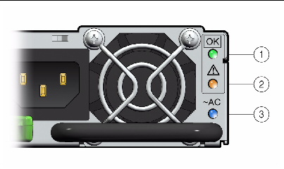
Each power supply contains a series of LEDs on the back panel of the system.
FIGURE 3-11 Sun Fire X4170 Server Power Supply Status LEDs

FIGURE 3-12 Sun Fire X4270 and X4275 Servers Power Supply Status LEDs

|
Caution - Hazardous voltages are present. To reduce the risk of electric shock and danger to personal health, follow the instructions. |
1. Identify which power supply (0 or 1) requires replacement.
A lit Service Action Required LED on a power supply indicates that a failure was detected.
2. Gain access to the rear of the server where the faulty power supply is located.
3. Release the cable management arm (CMA) (FIGURE 3-13).
The CMA is located at the rear of the server rack.
FIGURE 3-13 Releasing the Cable Management Arm

a. Press and hold the tab [1].
b. Rotate the cable management arm out of the way so that you can access the power supply [2].
4. Disconnect the power cord from the faulty power supply.
5. Grasp the power supply handle and press the release latch (FIGURE 3-14 and FIGURE 3-15).
6. Pull the power supply out of the chassis.
FIGURE 3-14 Power Supply Release Handle on Sun Fire X4170 Server

FIGURE 3-15 Power Supply Release Handle on Sun Fire X4270 and X4275 Servers

1. Align the replacement power supply with the empty power supply chassis bay.
2. Slide the power supply into the bay until it is fully seated.
3. Reconnect the power cord (or cords) to the power supply (or supplies).
Verify that the AC Present LED is lit.
4. Close the CMA, inserting the end of the CMA into the rear left rail bracket (FIGURE 3-13).
5. Verify that the following LEDs are not lit:
| Note - See Sun Fire X4170, X4270, and X4275 Servers Front Panel Features and Sun Fire X4170, X4270, and X4275 Servers Back Panel Features for more information about identifying and interpreting system LEDs. |
| Sun Fire X4170, X4270, and X4275 Servers Service Manual | 820-5830-13 |
Copyright © 2010, Oracle and/or its affiliates. All rights reserved.


