A P P E N D I X  D

Connecting to the 2510 Array with Other Topologies

This appendix describes connecting data hosts to the Sun StorageTek 2510 Array with topologies other than the basic ones listed in Chapter 4. It contains the following section:


Connecting to the 2510 Array with Other Topologies

Chapter 5 showed the two most common duplex cabling topologies:

This section shows more examples of the above and adds:

Host Cabling Configurations - Single Controller

The following figures demonstrate single controller host cabling configurations:


FIGURE D-1 Direct Connection - One Host Connected to a Single Controller
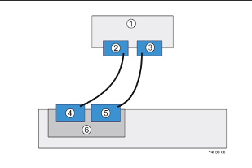
Figure showing a direct connection: One host connected to a single controller.

1

Host

4

Host Port 1

2

NIC 1

5

Host Port 2

3

NIC 2

6

Controller A

FIGURE D-2 Direct Topology - Two Hosts Connected in a Single Path
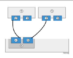
Figure showing a direct connection: One host connected to a single controller.

 Figure showing a direct topology: Two hosts connected in a single path.

1

Hosts

4

Host Port 1

2

NIC 1

5

Host Port 2

3

NIC 2

6

Controller A

You can connect one or more hosts to a controller tray. The hosts can run the same operating system or each host can run a different type of operating system.


FIGURE D-3 Fabric Topology - Two Hosts Connected to the Controller Through a Switch
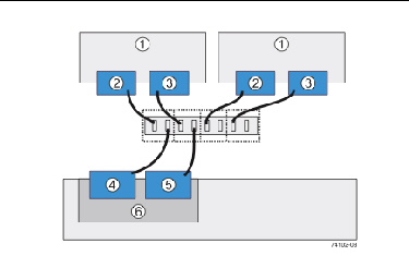
Figure showing a fabric topology: Two hosts connected to the controller through a switch.

1

Hosts

4

Host Port 1

2

NIC 1

5

Host Port 2

3

NIC 2

6

Controller A

FIGURE D-4 Mixed Topology - Three Hosts Connected Through a Switch or Connected Directly
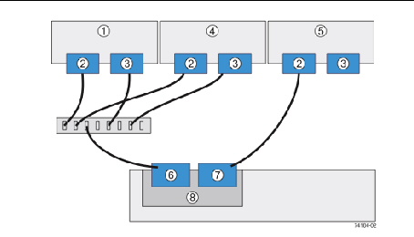
Figure showing a fabric topology: Two hosts connected to the controller through a switch.

 Figure showing a mixed topology: Three hosts connected through a switch or connected directly.

1

Host 1

5

Host 3

2

NIC 1

6

Host Port 1

3

NIC 2

7

Host Port 2

4

Host 2

8

Controller A

Host Cabling Configurations - Dual Controller

The following figures demonstrate dual controller host cabling configurations:


FIGURE D-5 Direct Topology - One Host Connected to Each Controller
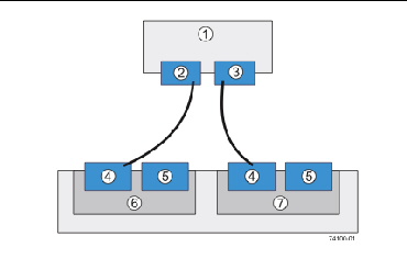
Figure showing a direct topology: One host connected to each controller.

1

Host

5

Host Port 2

2

NIC 1

6

Controller A

3

NIC 2

7

Controller B

4

Host Port 1

FIGURE D-6 Mixed Topology - Three Hosts Connected Through a Switch or Connected Directly
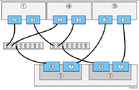
Figure showing a direct topology: One host connected to each controller.

 Figure showing a mixed topology: Three hosts connected through a switch or connected directly.

1

Host 1

4

Host 2

7

Host Port 2

2

NIC 1

5

Host 3

8

Controller A

3

NIC 2

6

Host Port 1

9

Controller B