| C H A P T E R 3 |
|
Connecting the Management Host and Data Hosts |
This chapter describes Sun Storage 6580 and 6780 Arrays cable connections for the management host and data hosts. It contains the following sections:
| Note - You need to know the storage management method that you plan to use before you install the software, connect the cables, and use the storage management software. |
| Note - If you use the out-of-band management method but do not have a DHCP server, you must manually configure your controllers. |
There are two types of management paths:
By default, the management host communicates with the array out-of-band over Ethernet. An out-of-band management method sends commands to the storage array through the Ethernet connections on the controller.
To set up an out-of band connection:
1. Connect the Ethernet cables between Ethernet port 1 on Controller A and Controller B and the management host (see Connection Options Between the Array and Management Host).
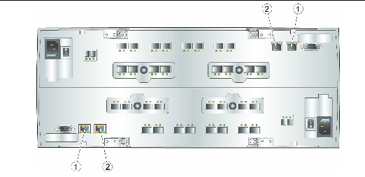
| Note - You can only use Ethernet port 1 to connect to a management host. Ethernet port 2 is reserved for service use. |

2. Assign a static IP address or dynamic IP address to each controller.
a. If you have a DHCP server, see Configuring a DHCP Server for instructions.
b. If you do not have a DHCP server, you will manually configure the controllers as described in Configuring IP Addressing.
You can establish a connection between the management host and Ethernet port 1 of an array controller in one of three ways:
To attach the Ethernet ports to the local area network (LAN) of the management host:
1. Locate the Ethernet port 1 for Controller A and Controller B at the back of the controller tray (FIGURE 3-1).
2. Connect an Ethernet cable to Ethernet port 1 of each controller.
3. Connect the other end of each Ethernet cable to the LAN on which your management host resides (preferably on the same subnet).
To attach the Ethernet ports and the management port Ethernet interface to an Ethernet hub on a private subnet:
1. Locate Ethernet port 1 on Controller A and Controller B at the back of the controller tray (FIGURE 3-1).
2. Connect an Ethernet cable to Ethernet port 1 of each controller.
3. Connect the other end of each Ethernet cable to an Ethernet hub.
4. Connect an Ethernet port on the management host to the Ethernet hub.
Use this method to establish temporary IP connectivity between the management host and the controller’s Ethernet ports.
To attach the Ethernet ports directly to the management host using a cross-over cable, follow these steps for each controller, as necessary:
1. Locate Ethernet port 1 on either Controller A or Controller B at the back of the controller tray (FIGURE 3-1).
2. Obtain and connect an Ethernet cross-over cable to Ethernet port 1 of the controller.
3. Connect the other end of the Ethernet cross-over cable to the LAN on which your management host resides.
You can configure in-band management using a Fibre Channel (FC) connection between a data host and the array. An in-band connection uses the data path between the array and host for management traffic.
1. Install CAM software on at least one of the network-attached hosts. See the Sun StorageTek Common Array Manager Installation Guide for installation instructions.
2. Connect two in-band FC cables between HBAs on the data host and the array (one cable to each controller). You can connect the data host HBAs directly to the array or through FC switches.
You can connect data hosts to access the Sun Storage 6580 or 6780 array through Fibre Channel (FC) switches to the array or directly to the array.
The Sun Storage 6580 and 6780 arrays have eight data host pair connections per controller. To maintain redundancy, connect two data paths from each host, one to each controller.
1. Locate the data host ports (Small Form-factor Pluggable [SFP] transceivers) at the back of the controller tray.
FIGURE 3-2 Controller Tray Data Host Ports

2. Connect each fiber-optic cable to the data host ports of Controller A and Controller B.

|
Caution - Fiber-optic cables are fragile. Do not bend, twist, fold, pinch, or step on the fiber-optic cables. Doing so can degrade performance or cause data loss. |
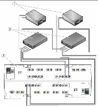
3. Connect the other end of each cable to the external switch as shown in the graphics that follow.
4. Connect the cables from the switch to the HBAs for each data host.
5. Affix a label to each end of the cable to identify the connection. Include the following information on the label:
FIGURE 3-3 Data Host Through FC Switch Connections

|
Redundant connections to Controller A (top) and Controller B (bottom) |
|||
A direct point-to-point connection is a physical connection in which the data host HBAs are cabled directly to the array’s host ports.
1. Locate the data host ports at the back of the controller tray.
2. Connect a fiber-optic cable to each data host port on Controller A and Controller B that you intend to use.

|
Caution - Fiber-optic cables are fragile. Do not bend, twist, fold, pinch, or step on the fiber-optic cables. Doing so can degrade performance or cause data loss. |
3. Connect the other end of each fiber-optic cable to a data host HBA.
FIGURE 3-4 Data Host Direct Connections
|
Redundant connections to Controller A (top) and Controller B (bottom) |
4. Affix a label to each end of the cable to identify the connection. Include the following information on the label:
5. Check the status of each connection. If you see a fault, use CAM to diagnose and correct the problem.
When you finish connecting all cables, close the front and back cabinet doors.
After you have connected the management host and data hosts, you are ready to configure IP addressing, if necessary, as described in Chapter 5.
Copyright © 2009 Sun Microsystems, Inc. All rights reserved.