| C H A P T E R 2 |
 Network Connection, Environmental, and Electrical Specifications
 |
This chapter contains the network connection, environmental, and electrical specifications for the SPARC Enterprise M4000/M5000 servers from Oracle and Fujitsu.
This section provides an overview of the midrange servers network setup for server startup and network connections. For more information on network connection, refer to the SPARC Enterprise M4000/M5000 Servers Installation Guide.
The serial port on the eXtended System Control Facility Unit (XSCFU) is used to monitor the boot process and to modify the XSCFU network settings so that the local area network (LAN) ports can be used to connect to a system control network.
A system control network is a secure LAN that connects the XSCFU to the system administrator’s management console. This connection can be done directly but is usually done through a hub or switch specific to the system control network. Administration directly over the serial port is used to initially configure the LAN ports.
The following network connections must be available:
| Note - The XSCF Ethernet port is IEEE 802.3i and IEEE 802.3u compliant. This requires auto-negotiation for the port into which it terminates. |
The following information is required when installing midrange servers:
In determining the system control network configuration, consider the following:
There are three common system control network configurations depending upon the site requirements:
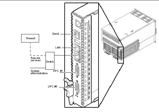
Configuration A (Basic) - Only one of the two LAN ports is used, leaving the serial port and the other LAN port for use as maintenance ports. The same switch is used for system administration and remote services, so switch failure means system control network failure.
FIGURE 2-1 Configuration A (Basic)
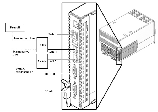
Configuration B (Limited Redundancy) - Both LAN ports are used, one for system administration and the second for remote messaging. If one switch goes down, errors can still be reported. The serial port and a port on the remote services switch are available as maintenance ports.
FIGURE 2-2 Configuration B (Limited Redundancy)
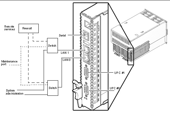
Configuration C (Maximum Redundancy) - Both LAN ports are used and each switch has a maintenance port that is connected to remote services, system administration. A failed switch causes no interruption in the system control network.
FIGURE 2-3 Configuration C (Maximum Redundancy)
For more information on connecting to a console, refer to the SPARC Enterprise M4000/M5000 Servers Installation Guide for your product.
This section describes the Uninterruptible Power Supply (UPS) interface which connects to and controls the UPS.
A UPS unit is used to provide a stable supply of power to the system in the event of a power failure or an extensive power interruption.
When a failure is detected in the supply of power, an error can be reported to the server through the signal cable connection between a UPC port on the server and a UPS that has the UPC interface. Then the server can execute emergency shutdown processing to safely shut down the system.
Prepare shielded and paired cables that have the following specifications:
This section describes signal definitions and electrical specifications.
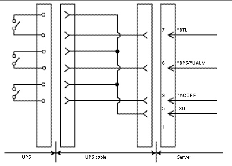
FIGURE 2-4 shows the signal line configuration when connected to a UPS.
TABLE 2-1 defines these signal lines.
FIGURE 2-4 Connection with UPS
|
Signal provides a warning of a low battery level and a pending UPS failure. |
|||
|
Signal indicates power failure at the commercial AC supply connector to the UPS |
|||
TABLE 2-2 and TABLE 2-3 list the electrical specifications for the UPS interface.
Limit the signal-line chatter period to 1ms or less.
The UPS cable specifications are as follows:
FIGURE 2-5 identifies pin signals of the UPC connector and the UPS cable.
Do not use the unused pins (pin number 2, 3, 4 and 8 in the following diagram). Cable side shown in FIGURE 2-5.
FIGURE 2-5 Corresponding Terminals in UPC Port and the UPS Cable
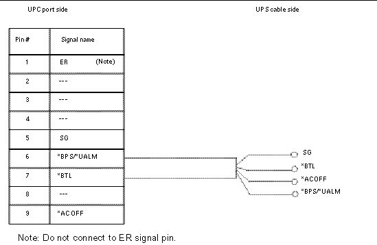
| Note - If you need UPC cables, make arrangements separately. For details, contact your sales representatives. |
Both midrange servers can be installed in an environment with the operating ranges shown in TABLE 2-4.
The design of your environmental control system--such as computer room air-conditioning units--must ensure that intake air to the servers complies with the limits specified in this section.
TABLE 2-4 lists the environmental requirements.
The environmental requirements listed in TABLE 2-4 reflect the test results of the server. The optimum conditions indicate the recommended operating environment. Operating the server for extended periods at or near the operating range limits or installing the server in an environment where it remains at or near the non-operating range limits could possibly increase the failure rate of hardware components significantly. In order to minimize the occurrence of system failure due to component failure, set temperature and humidity in the optimal ranges.
|
Relative
|
|||
|
Altitude
|
|||
|
5˚C to 35˚C (41˚F to 95°˚F):
5˚C to 33˚C (41˚F to 91.4°˚F):
5˚C to 31˚C (41˚F to 87.8°˚F):
5˚C to 29˚C (41˚F to 84.2°˚F):
|
| Note - In order to minimize any chance of downtime due to component failure, use the optimal temperature and humidity ranges. |
The ambient temperature range of 21°C to 23°C (70°F to 74°F) is optimal for server reliability and operator comfort levels. Most computer equipment can operate within a wide temperature range, but a level near 22°C (72°F) is desirable because it is easier to maintain safe associated relative humidity levels at this temperature. Operating in this temperature range provides a safety buffer in the event the air conditioning systems go down for a period of time.
Ambient relative humidity levels between 45 percent and 50 percent are the most suitable for safe data processing operations. Most data processing equipment can operate within a fairly wide environmental range (20 percent to 80 percent), but the optimal goal should be between 45 percent to 50 percent for the following reasons:
Electrostatic discharge (ESD) is easily generated and less easily dissipated in areas where the relative humidity is below 35 percent. ESD becomes critical when humidity levels drop below 30 percent. The 5 percent relative humidity range might seem unreasonably tight when compared to the guidelines used in typical office environments or other loosely controlled areas. However, it is not as difficult to maintain in a data center because of the high efficiency vapor barrier and low rate of air changes normally present.
The allowable comtaminations in the M4000/M5000 servers are listed in TABLE 2-5.
|
The installation site shall not be within 0.5 km of the ocean or coastal areas (unless the computer |
This section describes the CPU types and the maximum power consumption of the server.
There are four types of CPU. The power specifications of the M4000 and M5000 servers vary depending on the CPU type and the system configuration.
TABLE 2-6 and TABLE 2-7 list the specifications of maximum power consumption, apparent power, and heat dissipation by the type of CPU. The figures represent the system configuration described below the tables, in which every CPU Modules (CPUM) is mounted with the same CPU.
| Note - Values in TABLE 2-6 and TABLE 2-7 are rounded to the nearest whole numbers. |
This section provides guidelines and requirements for cooling the midrange servers. See TABLE 2-8 for the electrical and cooling specifications.
Be aware of the following server cooling rules and guidelines:
| Note - The power numbers in TABLE 2-8 are maximums and are based on fully configured servers. Actual numbers might vary according to your server configuration. |
|
Rush current per PSU[5] |
||
|
Leakage current per PSU[6] |
||
| Note - For servers that have the plug with lock function, confirm that a 20A overcurrent protection device is available outside the server. If one is not available, prepare an external 20A overcurrent protection that can be achieved by means of no-fuse breakers (NFBs) or fuses. The plug with lock function refers to plugs other than grounding-type ones with two parallel blades, such as the NEMA L6-30, L6-20, L6-15, and L5-15. |
The maximum rate of heat release from fully configured midrange servers is listed in TABLE 2-10.
Both midrange servers have been designed to function while mounted in a natural convection airflow. The following rules must be followed to meet the environmental specification.
Ensure that additional equipment installed in the equipment rack does not exceed environmental limits at the air inlet. The environmental limits assume the server is operating in the equipment rack with ventilated doors closed.
The airflow indicator indicates the amount of air exhausted from the server while the M4000/M5000 servers are up and running. The values do not include the peripheral devices. To display the amount of exhaust air, use the showenvironment air command.
| Note - The showenvironment air command displays the calculated airflow based on the fan speed such as Low speed or High speed etc. The fan speed is displayed by the showenvironment Fan command. |
For details of the showenvironment(8) command, refer to the man page. For installation details of the M4000/M5000 servers, see the SPARC Enterprise M4000/M5000 Servers Site Planning Guide and the SPARC Enterprise M4000/M5000 Servers Installation Guide.
You can also obtain the exhaust air data using the SNMP agent function. To obtain the data of exhaust air using the SNMP agent function, install the latest XSCF extension MIB definition file to the SNMP manager. For details on the XSCF extension MIB definition file, see the SPARC Enterprise M3000/M4000/M5000/M8000/M9000 Servers XSCF User’s Guide
To prevent catastrophic failures, the design of your power system must ensure that adequate power is provided to your midrange servers. Use dedicated AC breaker panels for all power circuits that supply power to your server. Electrical work and installations must comply with applicable local, state, or national electrical codes.
Qualified equipment racks housing these midrange servers require their own customer-supplied circuit breaker and AC receptacle for each power cord. Provide a stable power source, such as an uninterruptible power system (UPS), to reduce the possibility of component failures. If the computer equipment is subjected to repeated power interruptions and fluctuations, it is susceptible to a higher component failure rate than it would be with a stable power source.
| Note - If the appropriate electrical receptacle is not available in your country, the connector may be removed from the cord. The cord can then be permanently connected to a dedicated branch circuit by a qualified electrician. Check local electrical codes for proper installation requirements. |
Both midrange servers are shipped with grounding-type (three-wire) power cords. Always connect the cords into grounded power outlets. Each power cord will also supply your server with proper earth ground.
Contact your facilities manager or a qualified electrician to determine what type of power is supplied to your building.

Copyright © 2007,2011, Oracle and/or its affiliates. All rights reserved. FUJITSU LIMITED provided technical input and review on portions of this material.