Configuring and Using IPMP in the Service Domain
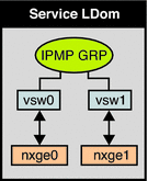
IPMP can be configured in the service domain by configuring virtual switch interfaces into a group. The following diagram shows two virtual switch instances (vsw0 and vsw1) that are bound to two different physical devices. The two virtual switch interfaces can then be plumbed and configured into an IPMP group. In the event of a physical link failure, the virtual switch device that is bound to that physical device detects the link failure. Then, the virtual switch device sends notification of this link event to the IP layer in the service domain, which results in failover to the other virtual switch device in the IPMP group.
Figure 7–5 Two Virtual Switch Interfaces Configured as Part of IPMP Group

- © 2010, Oracle Corporation and/or its affiliates
