| Exit Print View | |
Sun Datacenter InfiniBand Switch 648 Topic Set |

|
Documentation, Support, and Training
Understanding the Installation
Fabric Card Handling Guidelines
Fabric Card and Line Card Fillers
Suggested Tools for Installation
Antistatic Precautions for Installation
Installing the InfiniBand Software Stack
Install the HPC Software Suite
Remove the Shipping Carton Contents
Unsecure the Chassis From the Pallet
Install the Rail Assemblies in the Rack
Install the Chassis in the Rack
Inspecting the Midplane for Installation
Identify the Midplane Fabric Card Connectors
Inspect the Pins on the Rear Side of the Midplane
Identify the Midplane Line Card Connectors
Inspect the Pins on the Front Side of the Midplane
Inspecting the Fabric Cards for Installation
Identify the Fabric Cards for Installation
Inspect the Fabric Card Chassis for Installation
Inspect the Fabric Card Retainer Bolts for Installation
Inspect the Fans for Installation
Inspect the Fabric Card XBOW Connectors for Installation
Inspecting the Line Cards for Installation
Identify the Line Cards for Installation
Inspect the Line Card Chassis for Installation
Inspect the Line Card Retainer Bolts for Installation
Inspect the Line Card XBOW Connectors for Installation
Inspect the Line Card CXP Connectors for Installation
Inspecting the InfiniBand Cables for Installation
Identify the InfiniBand Cable for Installation
Inspect the InfiniBand Cable Hardware for Installation
Inspect the InfiniBand Cable Connectors for Installation
Install the Midplane Stiffener
Install the Fabric Cards or Fabric Card Fillers
Install the Line Cards or Line Card Fillers
Check the Power Supply Status LEDs
Access the CMC From the Serial Management Port
Set the Initial UBoot Parameters
Access the CMC From the Network Management Port
Display the CMC FRU ID Information
Verify the Power Supply Status
Identify the Power Supply Addresses
Display the Power Supply FRU ID Information
Enable the Fabric Cards for Installation
Create the guid.txt File for Installation
Power On the Fabric Cards for Installation
Check the Fabric Card Status LEDs
Identify the Fabric Card Addresses
Display the Fabric Card FRU ID Information
Enable the Line Cards for Installation
Power On the Line Cards for Installation
Check the Line Card Status LEDs
Identify the Line Card Addresses
Display the Line Card FRU ID Information
Check the CXP Connector Status LEDs
Identify the CXP Connector Addresses
Display the InfiniBand Cable FRU ID Information
Verifying the InfiniBand Fabric
Discover the InfiniBand Fabric Topology
Perform Diagnostics on the InfiniBand Fabric
Validate the InfiniBand Fabric and Report Errors
Understanding ILOM on the Switch
Note - This procedure describes cabling the switch in a center split, left-right symmetrical configuration.
Identify the prerequisite and subsequent tasks you must perform in conjunction with this procedure, to install the switch.
See the table in ![]() Installation Sequence.
Installation Sequence.
Bring the cables to the switch.
Install a cable shelf into the slot below the lowest line card.
Lift the cable shelf into a horizontal orientation, with the long rolled edge towards you.
Locate where you want to install the cable shelf.
Move the cable shelf between and just above the branches of the cable tree for the slot where you want to install the shelf.
Continue to move the shelf in, then lower the shelf into the tabs of the branches.
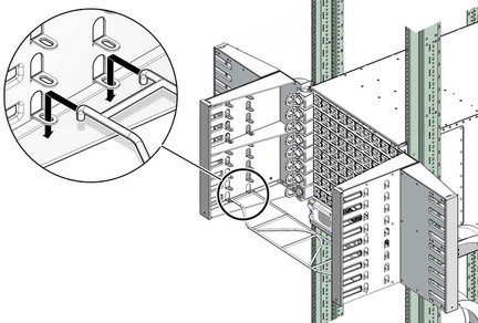
Note - Install cable shelves only as they are needed. If all cable shelves are installed before the switch is cabled, the shelves’ presence makes cabling difficult.
Plug the first cable into the CXP connector at 11B.
Note - For each connector group, A is the upper connector, B is the lower connector.
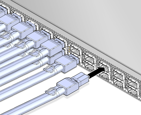
Remove the protective cap from the connector and visually inspect the cable connector.
The shell should not be bent and should be parallel to the inner boards. If the connector is bent or damaged, use a different cable.
Ensure that the retraction strap is forward.
Orient the cable connector to the line card CXP receptacle squarely and horizontally.
Ensure that the upper shell just touches the underside of the top of the receptacle on the line card.
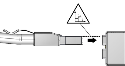
Slowly move the connector in.
As you slide the connector in, the top of the shell should scrape against the underside of the top of the CXP receptacle.
Continue to push the connector in until the hooks catch onto the top of the receptacle.
Curve the cable to the right through the branches of the cable tree.
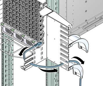
 | Caution - Do not allow any copper core InfiniBand cable to bend tighter than a 5 inch (127 mm) radius. Do not allow any optical InfiniBand cable to bend tighter than a 3.4 inch (85 mm) radius. Tight bends can damage the cable internally. |
Place the cable over the cable curve and move the cable in toward the rack.
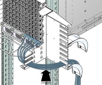
Repeat ![]() Step 4 for the second cable at CXP connector 0B.
Step 4 for the second cable at CXP connector 0B.
Curve the cable to the left through the branches of the cable tree.
 | Caution - Do not force a bend radius of less than 5 inches (127 mm). Any bend tighter than this damages the inner fibers of the cable, rendering it useless. |
Place the cable over the cable curve and move the cable in toward the rack.
Repeat ![]() Step 4 for the third cable at CXP connector 10B.
Step 4 for the third cable at CXP connector 10B.
Curve the cable to the right through the branches of the cable tree, next to the cable already there.
Place the cable over the cable curve and move the cable against the cable already there.
Repeat ![]() Step 4 for the fourth cable at CXP connector 1B.
Step 4 for the fourth cable at CXP connector 1B.
Curve the cable to the left through the branches of the cable tree, next to the cable already there.
Place the cable over the cable curve and move the cable against the cable already there.
Repeat ![]() Step 4 for cables connecting to CXP connectors 9B, 2B, and so on,
to and including 6B and 5B.
Step 4 for cables connecting to CXP connectors 9B, 2B, and so on,
to and including 6B and 5B.
Place the cables next to the cables that are already there.
Repeat ![]() Step 4 for cables connecting to CXP connectors 11A, 0A, 10A, 1A, and
so on, to and including 6A and 5A.
Step 4 for cables connecting to CXP connectors 11A, 0A, 10A, 1A, and
so on, to and including 6A and 5A.
Place the cables on top of the cables that are already there.
When you have finished for the lowest line card, repeat from ![]() Step 3 through
Step 3 through
![]() Step 17 for the remaining line cards, working your way up.
Step 17 for the remaining line cards, working your way up.
Note - There are two cable curves on each side of the switch. The cables from line cards 0 through 4 route over the lowest cable curve. The cables from line cards 5 through 8 route over the next cable curve up.
Install the EMI screen.
Verify the cabled CXP connector status LEDs indicate a link.
The Link LED should be lit and not flash. See ![]() Check the CXP Connector Status LEDs.
Check the CXP Connector Status LEDs.