| Exit Print View | |
Sun Datacenter InfiniBand Switch 72 User’s Guide |

|
Documentation, Support, and Training
Understanding Switch Specifications
Understanding InfiniBand Cabling
Understanding the Installation
Install the Switch in the Rack
Accessing the Management Controller
Access the Management Controller From the Network Management Port
Access the Management Controller From the USB Management Port
Verifying the InfiniBand Fabric
Administrative Command Overview
Monitoring the InfiniBand Fabric
Controlling the InfiniBand Fabric
Understanding Service Procedures
The switch has two connectors for network communication or serial communication with the management controller.
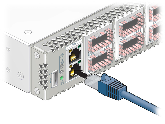
The network management connector, labeled NET, is a 100 BASE-T Ethernet interface. This connector is preferred because it permits remote management of the switch over the Ethernet network.
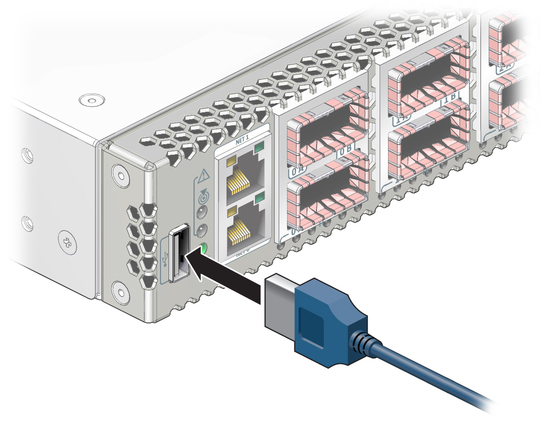
The USB management connector, labeled USB, is the second choice for communication with the management controller in the switch. The management console can be a serial terminal, a system running a TIP connection, or other serial device which communicates with the management controller through a USB-to-serial adapter. The serial parameters for communication with the USB-to-serial adapter is typically 115600, 8, N, 1.
Identify the prerequisite and subsequent installation tasks that you must perform in conjunction with this procedure.
Connect the network management cables from the management console to the connectors labeled NET.

Configure the DHCP server with the MAC address of the management controller.
The MAC address is printed on the customer information (yellow) sheet on the outside of the switch shipping carton and on the pull-out tab on the left side front of the switch chassis, adjacent to power supply 0.
(Optional) Connect the serial management cables from the management console to the USB-to-serial adapter, and from the adapter to the connector labeled with the USB symbol.

Route the management cables so that they do not interfere with other cables, with servicing the switch, or with other systems.
Prepare the management console for communication with the management controller.
Power on the switch.