| C H A P T E R 2 |
|
ILOM 3.0 Platform Features for Sun Blade X6270 Server Module |
This chapter contains information about ILOM 3.0 features that are specific to the Sun Blade X6270 Server Module.
The following topics are discussed in this chapter:
| Note - The ILOM platform-specific features described in this chapter for the Sun Blade X6270 Server Module are supported in addition to the common ILOM 3.0 features supported for all x64 servers. |
By default, you connect to the server module's service processor (SP) using the out-of-band network management port (NET MGT). The ILOM sideband management feature enables you to select either the NET MGT port or one of the server module's Gigabit Ethernet ports (NET 0 or 1), which are in-band, or sideband ports, to send and receive ILOM commands to and from the server SP.
The advantage of using a sideband management port to manage the server’s SP is that one less cable connection and one less network session is needed. In configurations where a great number of servers are being managed, such as data centers, sideband management can represent a significant savings in hardware and network utilization.
You can configure sideband management using either the web interface, the command-line interface (CLI), the BIOS, or IPMI. For instructions, see the following sections:
When sideband management is enabled in ILOM, the following conditions might occur:
| Note - If the ports are configured as switch ports and participate in the Spanning Tree Protocol (STP), you might experience longer outages due to spanning tree recalculation. |
|
1. Log in to the ILOM web interface.
2. In the ILOM web interface, select Configuration --> Network.
The Network Settings page appears.

3. In the Network Settings page, do the following:
a. Select DHCP to acquire the IP address automatically or specify the appropriate IP address.
b. Click the Management Port drop-down list and select the desired management port.
The drop-down list enables you to change to any one of the two Gigabit Ethernet ports, /SYS/SP/NETn, where n is 0 or 1.
The SP NET MGT port, /SYS/SP/NET0, is the default.
c. Click Save for the changes to take effect.
|
1. Do one of the following to connect to ILOM using the CLI:
For instructions, see the Sun Blade X6270 Server Module Installation Guide (820-6175) or the ILOM Documentation Collection, which is available online at http://docs.sun.com/app/docs/prod/int.lights.mgr30#hic.
The default password for the root account is changeme.
The ILOM CLI prompt appears (->).
2. To show the current port settings, type:
The network properties appear. For example:
In the above output the macaddress is the same as the outofbandmacaddress and the managementport is set to the default /SYS/SP/NET0.
3. To set the SP management port to a sideband port, type:
-> set /SP/network pendingmanagementport=/SYS/MB/NETn
The network properties appear and show that the change has taken effect. For example:
In the above output the macaddress matches the sidebandmacaddress, and the managementport matches the pendingmanagementport.
|
You can access the BIOS Setup utility menus from the following interfaces:
To configure sideband management using the host BIOS Setup utility, perform the following steps:
1. Power on or power cycle the server.
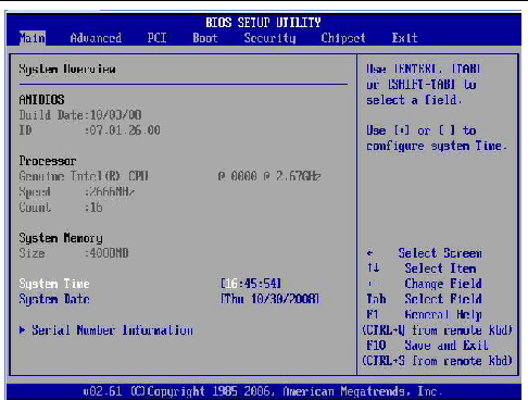
2. To enter the BIOS Setup utility, press the F2 key while the system is performing the power-on self-test (POST).
The BIOS Setup utility appears.

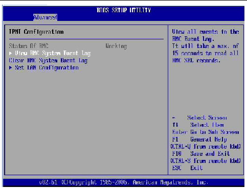
3. In the BIOS Setup utility dialog, select Advanced --> IPMI Configuration.
The IPMI Configuration menu appears.

4. In the IPMI Configuraton menu, select the Set LAN Configuration option.
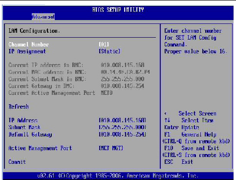
The LAN Configuration menu appears.

5. In the LAN Configuration menu, do the following:
a. Select the option for the Active Management Port and press Enter.
A tab appears listing the available port settings (Net0 and Net1) for sideband management.
b. In the tab, select the appropriate port setting for Sideband Management, then select Commit for the change to take effect.
When a server module component fails, the server SP generates a fault that is captured by the fault management function in ILOM. The system automatically clears the server component faults when the server module is cold-booted.
Other faults captured by the fault management function in ILOM include faults generated by the chassis monitoring module (CMM). These faults occur when other components in the chassis fail, for example:
Chassis related faults are not automatically cleared by the system. You must manually clear these faults in the Fault Management function on the ILOM CMM. After you have cleared the faults reported by the CMM, the chassis related faults are then automatically cleared by the system in the Fault Management function on the ILOM SP.
You can use either the ILOM web interface or the command-line interface (CLI) to manually clear faults. For information on how to use the ILOM web interface or the CLI to clear faults, see the following guides:
You can switch the serial port output of the Sun Blade X6270 Server Module between the SP console (NET MGT) and the host console (COM1). By default, the SP console is connected to the system serial port. This feature is beneficial for Windows kernel debugging, as it enables you to view non-ASCII character traffic from the host console.
You can switch serial port output using either the ILOM web interface or the ILOM command-line interface (CLI). For instructions, see the following sections:
|
1. Log in to the ILOM web interface.
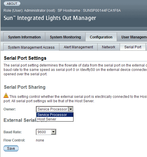
2. In the ILOM web interface, select Configuration --> Serial Port.
The Serial Port Settings page appears.

3. In the Serial Port Settings page, select Host Server as the serial port owner.
By default, Service Processor is selected.
4. Click Save for the changes to take effect.
5. Use a dongle cable to connect the serial host to the server.
For details on how to use a dongle cable to attach devices to the server, see the Sun Blade X6270 Server Module Service Manual (820-6178).
|
2. To set the serial port owner, type:
-> set /SP/serial/portsharing /owner=host
3. Use a dongle cable to connect a serial host to the server.
For details on how to use a dongle cable to attach devices to the server, see the Sun Blade X6270 Server Module Service Manual (820-6178).
The power management function in ILOM 3.0 enables you to monitor power consumption metrics from the command-line interface (CLI) or web interface. The following power management metrics are common to all Sun servers:
For additional information about the common power management metrics provided for all Sun servers, see the ILOM 3.0 Documentation Collection at http://docs.sun.com/app/docs/prod/int.lights.mgr30#hic.
Also refer to the Sun Integrated Lights Out Manager (ILOM) 3.0 Feature Updates and Release Notes (820-7329).
The server includes several sensors and indicators that report on hardware conditions. Many of the sensor readings are used to adjust the fan speeds and perform other actions, such as illuminating system indictor LEDs and powering off the server.
The following sections describe the sensors and indicators that ILOM monitors for the Sun Blade X6270 Server Module.
| Note - For information about how to obtain sensor readings or to determine the state of system indicators in ILOM, see the ILOM Documentation Collection, which is available online at http://docs.sun.com/app/docs/prod/int.lights.mgr30#hic. |
TABLE 2-1 describes the environmental sensors.
TABLE 2-2 describes the fan sensors.
TABLE 2-3 describes the power supply sensors.
TABLE 2-4 describes the presence sensors.
TABLE 2-5 describes the system indicators.
Copyright © 2009 Sun Microsystems, Inc. All rights reserved.