| Skip Navigation Links | |
| Exit Print View | |

|
Oracle Solaris Cluster 3.3 With SCSI JBOD Storage Device Manual |
| Skip Navigation Links | |
| Exit Print View | |

|
Oracle Solaris Cluster 3.3 With SCSI JBOD Storage Device Manual |
1. Installing a SCSI JBOD Storage Device
2. Maintaining a SCSI JBOD Storage Device
Sun StorEdge 3120 Cabling Diagrams
Installing a Sun StorEdge 3120 Storage Array
Sun StorEdge 3310 and 3320 SCSI Cabling Diagrams
Installing a Sun StorEdge 3310 or 3320 Storage Array
Adding a Sun StorEdge 3310 or 3320 Storage Array
SPARC: Sun StorEdge D1000 Cabling Diagrams
SPARC: Installing a Sun StorEdge D1000 Storage Array
SPARC: Adding a Sun StorEdge D1000 Storage Array
SPARC: Replacing a Sun StorEdge D1000 Storage Array
SPARC: Removing a Sun StorEdge D1000 Storage Array
SPARC: Sun StorEdge Multipack Cabling Diagrams
SPARC: Installing a Sun StorEdge Multipack Storage Array
SPARC: Adding a Sun StorEdge Multipack Storage Array
SPARC: Sun StorEdge Netra D130/S1 Cabling Diagrams
SPARC: Installing a Sun StorEdge Netra D130/S1 Storage Array
SPARC: Adding a Sun StorEdge Netra D130/S1 Storage Array
SPARC: Replacing a Sun StorEdge Netra D130/S1 Storage Array
SPARC: Removing a Sun StorEdge Netra D130/S1 Storage Array
SPARC: Sun StorEdge D2 Cabling Diagrams
SPARC: Installing a Sun StorEdge D2 Storage Array
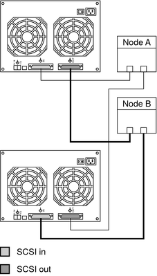
Connect the cables to the storage array, as shown in Figure 3-11.
Ensure that the entire SCSI bus length to each storage array conforms to the distances in Table 1-1. This measurement includes the cables to both nodes, as well as the bus length that is internal to each storage array, node, and host adapter. Refer to the documentation that shipped with the storage array for other restrictions about SCSI operation.
Figure 3-11 SPARC: Installing a Sun StorEdge Multipack Mirrored-Pair Configuration: An Example

Connect the single-ended SCSI cable between the node and the storage arrays, as shown in Figure 3-12.
Ensure that the entire SCSI bus length to each storage array conforms to the distances in Table 1-1. This measurement includes the cables to both nodes, as well as the bus length that is internal to each storage array, node, and host adapter. Refer to the documentation that shipped with the storage array for other restrictions about SCSI operation.
Figure 3-12 SPARC: Adding a Sun StorEdge Multipack Mirrored-Pair Configuration: Part 1

Connect the storage arrays to the host adapters by using single-ended SCSI cables, as shown in Figure 3-13.
Figure 3-13 SPARC: Adding a Sun StorEdge Multipack Mirrored-Pair Configuration: Part 2

Disconnect the SCSI cables from the storage array. Disconnect the SCSI cable on the SCSI OUT connector, and then disconnect the cable on the SCSI IN connector, as shown in Figure 3-14.
Figure 3-14 SPARC: Replacing a Sun StorEdge Multipack Storage Array

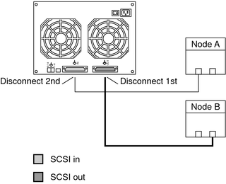
Disconnect the SCSI cables from the storage array. Disconnect the SCSI cables in the order that is shown in Figure 3-15.
Figure 3-15 SPARC: Removing a Sun StorEdge Multipack Storage Array
