This chapter includes:
Adapter Hardware Overview
The main features of the Sun Dual Port 4x QDR IB Host Channel Adapter PCIe ExpressModule are as follows:
- Compliant to the PCI ExpressModule Electromechanical Specification, Revision 1.1
- Compliant to the InfiniBand Architecture Specification, Release 1.2
- Two 40 Gbps 4x InfiniBand (IB) QSFP ports for connecting InfiniBand traffic (4x IB connectors)
- Media detect circuit supporting external InfiniBand active QSFP (copper) and fiber solutions
- EU Restriction of Hazardous Substances (RoHS) compliant
- IBTA (InfiniBand Trade Association) v1.2 compliant
- PCIe 2.0 adapter
- PCI Express expansion board with an x8 edge connector compatible to the PCI Express 1.0a specification
- Media detect circuit, which supports external InfiniBand fiber solutions
- 4x IB port speed support: 10 Gbps, 20 Gbps, or 40 Gbps (QDR - quad data rate)
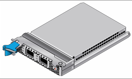
ExpressModule
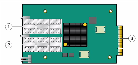
Figure shows components of the ExpressModule
FIGURE 1-1 ExpressModule

FIGURE 1-2 ExpressModule Without Metal Case

Figure Legend
|
1
|
InfiniBand Port 1
|
|
2
|
InfiniBand Port 2
|
|
3
|
PCI Express connector
|
I/O Interfaces
The ExpressModule includes the following interfaces:
- Two 4x InfiniBand QSFP connectors
- PCI ExpressModule to server or workstation connector
- I/O panel LEDs
InfiniBand Interface
The Sun Dual Port 4x QDR IB Host Channel Adapter PCIe ExpressModule is compliant with the InfiniBand Architecture Specification, Release 1.2. The ExpressModule has two compliant 4x InfiniBand ports (Port 1 and Port 2), each having four Tx/Rx pairs of SerDes. The ExpressModule provides access to these ports by means of two 4x InfiniBand connectors for external InfiniBand copper cables also compliant with the IBTA specification 1.2. Connector 1 connects to Port 1 of the device, while connector 2 connects to Port 2.
Furthermore, the ExpressModule is embedded with a media detect circuit that supports external InfiniBand active copper and fiber solutions.
PCI ExpressModule Interface
The ExpressModule is compatible with the PCI ExpressModule Electromechanical Specification, Revision 1.1. The device can be either a master initiating the PCI Express bus operations, or a slave responding to PCI bus operations.
LED Assignment
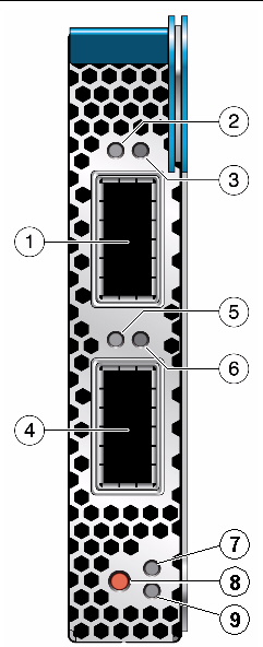
The ExpressModule has four LEDs located on the InfiniBand ports panel, with two LEDs for each 4x port. See FIGURE 1-3.
FIGURE 1-3 InfiniBand Ports and LEDs

Figure Legend
|
1
|
InfiniBand Port 1
|
|
2
|
Green LED for Port 1 (Physical Link)
|
|
3
|
Amber LED for Port 1 (Data Activity Link)
|
|
4
|
InfiniBand Port 2
|
|
5
|
Green LED for Port 2 (Physical Link)
|
|
6
|
Amber LED for Port 2 (Data Activity Link)
|
|
7
|
Power On Indicator
|
|
8
|
Hot Swap Button
|
|
9
|
Service Required Indicator
|
The pair of LEDs for each port have the meanings described in TABLE 1-1.
TABLE 1-1 LED Meanings
|
LED Color
|
LED Name
|
LED State
|
Meaning
|
|
Green
|
Physical Link
|
Lit
|
The link bringup process has successfully completed and the link width, link speed, link polarity, and link reversal have been negotiated with the neighbor port on the other end of the cable.
|
|
|
|
Unlit
|
A physical connection has not been established.
|
|
Amber
|
Data Activity
|
Steady light
|
Infiniband is discovered over the physical link, but no data is being passed.
|
|
|
|
Blinking light
|
Data is being passed.
|
|
|
|
Unlit
|
A physical or logical connection (or both) has not been established.
|
Power
The ExpressModule receives power from the server or workstation slot connector. All other required power is generated by ExpressModule switch-mode regulators. For power consumption see Appendix A.
Node GUID
A label on the Express Module enclosure displays the 64-bit GUID. This GUID uniquely identifies this device in the server and on the IB fabric.
Hardware and Software Requirements
For the latest list of supported platforms and operating systems, refer to the Sun Dual Port 4x QDR IB Host Channel Adapter PCIe ExpressModule Product Notes, part number 820-6540. This document is available at http://docs.sun.com.
| Sun Dual Port 4x QDR IB Host Channel Adapter PCIe ExpressModule User’s Guide
|
820-6539-13
|
   
|
Copyright © 2010, Oracle and/or its affiliates. All rights reserved.


