Sun Netra X4250 Server Overview
|
This chapter includes the following topics:
1.1 Product Description
The Sun Netra X4250 server (FIGURE 1-1) is a 2-rack unit (2U) server.
FIGURE 1-1 Sun Netra X4250 Server

The Sun Netra X4250 server is a scalable, reliable, high-performance, entry-level server, optimized for enterprise data centers. The server offers the following key features:
- Single or dual Intel® Xeon® L5408 quad core, 2.13 GHz processors for high-throughput and energy savings.
- High levels of system uptime through the processor and memory reliability, availability, and serviceability (RAS) features, coupled with redundancy of some system components, and support for hardware RAID (0+1).
- A space efficient, rack-optimized form factor 2U chassis.
- Unified server management though the use of the Sun Integrated Lights Out Manager (ILOM) system controller interface. ILOM integrates and manages x64 platforms with the same tool set, and in heterogeneous environments, using industry-standard element management tools and enterprise frameworks.
1.1.1 Features at a Glance
TABLE 1-1 lists the features of the Sun Netra X4250 server.
TABLE 1-1 Feature Specifications
|
Feature
|
Description
|
|
Processor
|
One or two Intel Xeon L5408 quad-core, 2.13 GHz socketed processors:
- 4 cores (32 threads)
- 8 cores (64 threads)
|
|
Memory Slots/Capacity
|
16 slots that can be populated with one of the following types of fully buffered (FB) DIMMS:
- 1 GB (16 GB maximum)
- 2 GB (32 GB maximum)
- 4 GB (64 GB maximum)
|
|
Internal Hard Drives
|
Two hot-pluggable 146 GB SAS drives with a DVD-RW drive
Or
Four hot-pluggable 146 GB SAS drives without a DVD-RW drive
Integrated hard drive controller supports RAID 0 and RAID 1.
|
|
Optical Media Drive
|
One, slot-loading, slimline DVD drive, supporting CD-R/W,
CD+R/W, DVD-R/W, DVD+R/W
|
|
Power Supplies
|
Two hot-swappable 660W AC/DC power supply units (PSUs) providing N+1 redundancy
|
|
Alarm
|
One Telco alarm
|
|
Cooling
|
Three high-power fans for processor, memory FB-DIMM, and PCI card cooling
Three low-power fans for hard drive and removable media drive cooling
|
|
Ethernet Ports
|
Four 1-GbE, RJ-45-based, autonegotiating ports (on two separate controllers)
Note - Two 10-GbE ports are available by adding a Sun 10-Gigabit Ethernet PCI-X Adapter.
|
|
PCI Express Interfaces
|
- One X8 PCIe full-length, full-height slot
- One X8 PCIe slot
- Two X4 PCIe slots
- One PCI-X full-length, full-height slot
- One PCI-X slot
|
|
USB Ports
|
Two USB 2.0 ports on rear panel.
|
|
Additional Ports
|
The following ports are located on the rear panel of the server:
- One RJ-45 serial management port (SER MGT) - the default connection to system controller
- One 10/100 Mbps Ethernet network management port (NET MGT) - connection to the system controller
- One Alarm port - connection to the alarm card
- One VGA port - connection to the host
|
|
Remote Management
|
Sun Integrated Lights Out Manager (ILOM)
|
|
Firmware
|
Firmware comprising:
- ILOM (system management)
- BIOS and POST
|
|
Cryptography
|
Processor integrated, cyptographic acceleration that supports industry standard security ciphers
|
|
Operating Systems
|
- Oracle Solaris 10 8/07 Operating System (preinstalled on disk 0) or newer
- Red Hat Enterprise Linux
- SUSE Linux
- MS Windows Server 2003
Refer to the server product notes for information on the minimum version of supported OS and required patches
|
1.1.2 Chassis Controls, LEDs, and Connectors
The following figures show the physical characteristics of the front and rear panels of the Sun Netra X4250 server (FIGURE 1-2, FIGURE 1-3, and FIGURE 1-5).
FIGURE 1-2 Front Panel With DVD
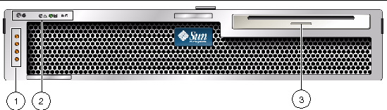
Figure Legend
|
No.
|
Description
|
Additional Information
|
|
1
|
Alarm status indicators
|
Top to bottom - Critical LED, Major LED, Minor LED, User LED
|
|
2
|
System status indicators
|
Left to right - Locator LED button, Service Required LED, System Activity LED, Power button
|
|
3
|
Removable media
|
In 2 hard drive configurations
|
FIGURE 1-3 Front Panel With Bezel Removed and Two HDDs

Figure Legend
|
No.
|
Description
|
Additional Information
|
|
1
|
Alarm status indicators
|
Also displayed with front bezel installed, see FIGURE 1-2.
|
|
2
|
System status indicators
|
Also displayed with front bezel installed, see FIGURE 1-2.
|
|
3
|
Hard drive 1
|
HDD 1
|
|
4
|
Hard drive 0
|
HDD 0
|
|
5
|
Hard drive LEDs
|
Top to bottom - OK to Remove LED, Service Required LED, Power OK LED
|
FIGURE 1-4 Front Panel With Bezel Removed and Four HDDs

Figure Legend
|
No.
|
Description
|
Additional Information
|
|
1
|
Alarm status indicators
|
Also displayed with front bezel installed, see FIGURE 1-2.
|
|
2
|
System status indicators
|
Also displayed with front bezel installed, see FIGURE 1-2.
|
|
3
|
Hard drive 2
|
HDD 2
|
|
4
|
Hard drive 3
|
HDD 3
|
|
5
|
Hard drive 1
|
HDD 1
|
|
6
|
Hard drive 0
|
HDD 0
|
|
7
|
Hard drive LEDs
|
Top to bottom - OK to Remove LED, Fault LED, Activity LED
|
FIGURE 1-5 Rear Panel Cable Connectors and LEDs

Figure Legend
|
No.
|
Description
|
Additional Information
|
|
1
|
Power Supply 0 LEDs
|
Top to bottom - Power OK LED, Service Required LED, DC Power LED
|
|
2
|
Power Supply 0
|
|
|
3
|
Power Supply 1 LEDs
|
Top to bottom - Power OK LED, Service Required LED, DC Power LED
|
|
4
|
Power Supply 1
|
|
|
5
|
System LEDs
|
Left to right - Locator LED button, Service Required LED, Power OK LED
|
|
6
|
Service processor serial management port
|
SER MGT
|
|
7
|
Service processor network management port
|
NET MGT
|
|
8
|
Gigabit Ethernet ports
|
Left to right - NET0, NET1, NET2, NET3
|
|
9
|
Alarm port
|
|
|
10
|
USB ports
|
Left to right - USB0, USB1
|
|
11
|
VGA port
|
Video
|
|
12
|
Slot 3
|
PCI-X
|
|
13
|
Slot 0
|
X8 PCIe (SAS controller)
|
|
14
|
Slot 4
|
PCI-X full-height, full-width
|
|
15
|
Slot 1
|
X4 PCIe
|
|
16
|
Slot 5
|
X8 PCIe full-height, full-width
|
|
17
|
Slot 2
|
X4 PCIe
|
| Note - The PCI card slots include two PCIe 15W (slots 1 and 2), one PCI-X 15W (slot 3), one PCI-X 25W (slot 4), and one PCIe 25W (slot 5) for a total of 5 PCI slots.
|
1.2 Server Diagnostics Overview
There are a variety of diagnostic tools, commands, and indicators you can use to monitor and troubleshoot a server:
- LEDs - These indicators provide a quick visual notification of the status of the server and of some of the FRUs.
- ILOM firmware - This system firmware runs on the service processor. In addition to providing the interface between the hardware and OS, ILOM also tracks and reports the health of key server components. ILOM works closely with POST and Solaris Predictive Self-Healing technology to keep the system up and running even when there is a faulty component.
- Power-on self-test (POST) - POST performs diagnostics on system components upon system power up and resets to ensure the integrity of those components. POST messages are displayed and logged in the Basic Input/Output System (BIOS) event logs. POST works with ILOM to take faulty components offline if needed.
- Solaris OS Only
- Solaris OS Predictive SelfHealing (PSH) - This technology continuously monitors the health of the CPU and memory, and works with ILOM to take a faulty component offline if needed. The Predictive SelfHealing technology enables Sun systems to accurately predict component failures and mitigate many serious problems before they occur.
- Log files and console messages - These items provide the standard Solaris OS log files and investigative commands that can be accessed and displayed on the device of your choice.
- SunVTS
 - An application that exercises the system, provides hardware validation, and discloses possible faulty components with recommendations for repair.
The LEDs, ILOM, Solaris OS PSH, and many of the log files and console messages are integrated. For example, a fault detected by the Solaris software will display the fault, log it, pass information to ILOM where it is logged, and depending on the fault, might light one or more LEDs.
1.2.1 Server LEDs
These LEDs provide a quick visual check of the state of the system.
1.2.1.1 Front and Rear Panel LEDs
The seven front panel LEDs (FIGURE 1-6) are located in the upper left corner of the server chassis. Three of these LEDs are also provided on the rear panel (FIGURE 1-7).
FIGURE 1-6 Location of the Bezel Server Status and Alarm Status LEDs

Figure Legend
|
No.
|
Description
|
Additional Information
|
|
1
|
User Alarm Status Indicator
|
Amber
|
|
2
|
Minor Alarm Status Indicator
|
Amber
|
|
3
|
Major Alarm Status Indicator
|
Red
|
|
4
|
Critical Alarm Status Indicator
|
Red
|
|
5
|
Locator LED Button
|
White
|
|
6
|
Service Required LED
|
Amber
|
|
7
|
Activity LED
|
Green
|
|
8
|
Power button
|
|
FIGURE 1-7 Rear Panel LEDs

Figure Legend
|
No.
|
Description
|
Additional Information
|
|
1
|
Power Supply 0 LEDs
|
Top to bottom - Locator LED, Service Required LED, Power OK LED
|
|
2
|
Power Supply 1 LEDs
|
Top to bottom - Locator LED, Service Required LED, Power OK LED
|
|
3
|
System LED
|
Left to right - Locator LED Button, Service Required LED, Power OK LED
|
|
4
|
Network Management port LEDs
|
Left to right - Link/Activity LED, Speed LED
|
|
5
|
Gigabit Ethernet port LEDs
|
Left to right - Link/Activity LED, Speed LED
|
| Note - The PCI card slots include two PCIe 15W (slots 1 and 2), one PCI-X 15W (slot 3), one PCI-X 25W (slot 4), and one PCIe 25W (slot 5) for a total of 5 PCI slots.
|
TABLE 1-2 lists and describes the front and rear panel LEDs.
TABLE 1-2 Front and Rear Panel LEDs
|
LED
|
Location
|
Color
|
Description
|
|
Locator LED Button
|
Front upper left and rear center
|
White
|
Enables you to identify a particular server. The LED is activated using one of the following methods:
- Issuing the setlocator on or off command.
- Pressing the button to toggle the indicator on or off.
This LED provides the following indications:
- Off - Normal operating state.
- Fast blink - The server received a signal as a result of one of the preceding methods.
|
|
Service Required LED
|
Front upper left and rear center
|
Amber
|
If on, indicates that service is required. The ILOM command show faulty provides details about any faults that cause this indicator to be lit.
|
|
Activity LED
|
Front upper left
|
Green
|
- On - Drives are receiving power. Solidly lit if drive is idle.
- Flashing - Drives are processing a command.
- Off - Power is off.
|
|
Power button
|
Front upper left
|
|
Turns the host system on and off. This button is recessed to prevent accidental server power-off. Use the tip of a pen to operate this button.
|
|
Alarm: Critical LED
|
Front left
|
Red
|
Indicates a critical alarm.
|
|
Alarm: Major LED
|
Front left
|
Red
|
Indicates a major alarm.
|
|
Alarm: Minor LED
|
Front left
|
Amber
|
Indicates a minor alarm.
|
|
Alarm: User LED
|
Front left
|
Amber
|
Indicates a user alarm.
|
|
Power OK LED
|
Rear center
|
Green
|
The LED provides the following indications:
- Off - The system is unavailable. Either the system has no power or ILOM is not running.
- Steady on - Indicates that the system is powered on and is running it its normal operating state.
- Standby blink - Indicates that the service processor is running while the system is running at a minimum level in Standby mode and is ready to be returned to its normal operating state.
- Slow blink - Indicates that a normal transitory activity is taking place. The system diagnostics might be running, or the system might be booting.
|
1.2.1.2 Hard Drive LEDs
The hard drive LEDs (FIGURE 1-8) are located on the front of each hard drive that is installed in the server chassis.
FIGURE 1-8 Hard Drive LEDs

Figure Legend
|
No.
|
Description
|
Color
|
Additional Information
|
|
1
|
OK to Remove
|
Blue
|
On - The drive is ready for hot-plug removal.
Off - Normal operation.
|
|
2
|
Fault
|
Amber
|
On - The drive has a fault and requires attention.
Off - Normal operation.
|
|
3
|
Activity
|
Green
|
On - The drive is receiving power. Solidly lit if drive is idle.
Flashing - The drive is processing a command.
Off - Power is off.
|
1.2.1.3 Power Supply LEDs
The power supply LEDs (FIGURE 1-9) are located on the rear of each power supply.
FIGURE 1-9 Power Supply LEDs

Figure Legend
|
No.
|
Description
|
Color
|
Additional Information
|
|
1
|
Power OK
|
Green
|
On - Normal operation. DC output voltage is within normal limits.
Off - Power is off.
|
|
2
|
Fault
|
Amber
|
On - Power supply has detected a failure.
Off - Normal operation.
|
|
3
|
Source OK
|
Green
|
On - Normal operation. Input power is within normal limits.
Off - No input voltage, or input voltage is below limits.
|
1.2.1.4 Ethernet Port LEDs
The ILOM management Ethernet port and the four 10/100/1000 Mbps Ethernet ports each have two LEDs, as shown in FIGURE 1-10 and described in the associated Figure Legend.
FIGURE 1-10 Ethernet Port LEDs

Figure Legend
|
No.
|
Description
|
Color
|
Additional Information
|
|
1
|
Link/Activity LED
|
Amber or
green
|
Steady On - A link is established.
Blinking - There is activity on this port.
Off - No link is established.
|
|
2
|
Speed LED
|
Green
|
Amber - The link is operating as a Gigabit connection (1000-Mbps)
Green - The link is operating as a 100Mbps connection.
Off - The link is operating as a 10/100Mbps connection.
|
| Note - The NET MGT port operates only in 100-Mbps or 10-Mbps so the speed indicator LED can be green or off (never amber).
|
1.2.2 Sun Integrated Lights Out Manager (ILOM)
The Sun Integrated Lights Out Manager (ILOM) is system management firmware that is preinstalled on some Sun server platforms. ILOM enables you to actively manage and monitor components installed in your server system. With ILOM, you can monitor and manage your system by viewing hardware configurations, monitoring system information, managing system alerts, and more. ILOM provides a browser-based web interface and a command-line interface, as well as an SNMP user interface and an IPMI user interface. ILOM automatically initializes as soon as power is applied to your system. ILOM will continue to run regardless of the state of the host operating system, making it a “lights-out” management system.
Some key features of ILOM include:
- Runs on its own processor and resources
- Allows for management of the server without consuming system resources
- Continues to provide management using standby power even when the server is powered off
- Provides an isolated management network separate from the data network
- Provides a concise view of hardware inventory and environmental information
- Provides the ability to control power, manage components, and access the host console
- Serves as an integration point for other management tools
- Enables the download of service processor (SP) firmware and BIOS changes
- Manages the inventory of hot-pluggable system components
ILOM enables you to remotely run diagnostics, such as power-on self-test (POST), that would otherwise require physical proximity to the server’s serial port. You can also configure ILOM to send email alerts of hardware failures, hardware warnings, and other events related to the server or to ILOM.
The service processor runs independently of the server, using the server’s standby power. Therefore, ILOM continues to function when the server operating system goes offline or when the server is powered off.
For information about configuring and using the ILOM service processor, refer to the latest Sun Integrated Lights Out Manager (ILOM) 2.0 User’s Guide and the Sun Integrated Lights Out Manager 2.0 Supplement for the Sun Netra X4250 Server. These documents are available online at:
http://docs.sun.com/app/docs/prod/server.nebs
1.2.3 POST and BIOS
For information about configuring BIOS, POST testing, POST codes, POST code checkpoints, and console redirection, see Appendix B, Configuring BIOS and POST.
1.3 Memory Configuration and Fault Handling
A variety of features play a role in how the memory subsystem is configured and how memory faults are handled. Understanding the underlying features helps you identify and repair memory problems. This section describes how the memory is configured and how the server deals with memory faults.
1.3.1 Memory Configuration
In the server memory there are 16 slots that hold DDR-2 memory FB-DIMMs in the following FB-DIMM sizes:
- 1 Gbyte (maximum of 16 Gbyte)
- 2 Gbyte (maximum of 32 Gbyte)
- 4 Gbyte (maximum of 64 Gbyte)
FB-DIMMs are installed in groups of 8, called ranks (ranks 0 and 1). At minimum, rank 0 must be fully populated with eight FB-DIMMs of the same capacity. A second rank of FB-DIMMs of the same capacity can be added to fill rank 1.
See Replacing FB-DIMMs for instructions about adding memory to a server.
1.3.2 Memory Fault Handling
The server uses an advanced ECC technology, called chipkill, that corrects up to 4 bits in error on nibble boundaries, as long as all of the bits are in the same DRAM. If a DRAM fails, the FB-DIMM continues to function.