| C H A P T E R 5 |
|
Installing the Sun StorageTek 5320 NAS Gateway System |
This chapter provides comprehensive instructions for connecting a Sun StorageTek 5320 NAS Gateway System or Sun StorageTek 5320 NAS Cluster Gateway System to SAN storage. It also provides initial configuration instructions for the system.
|
Note - If you are installing a different system, refer to the appropriate chapter. |
The Sun StorageTek 5320 NAS Gateway System can be directly attached or attached through fabric switches to a Sun StorageTek 6130/6140/6540 array, a Sun StorEdge 6920 system, Sun StorEdge FlexLine 200 and 300 series, or a Sun StorEdge 9970/9980/9985/9990 system (shortened to "Sun StorEdge 99xx system" in this chapter).
|
Note - Refer to the Sun StorageTek 5320 NAS Gateway System web page for the most current SAN storage information. |
This chapter contains the following sections:
|
Note - The Sun StorageTek 5320 NAS Gateway System and Sun StorageTek 5320 NAS Cluster Gateway System ship with the operating system installed. |
Before connecting the system, do the following:
You will configure storage after the Sun StorageTek 5320 NAS Gateway System is installed and set up.
To set up the Sun StorageTek 5320 NAS Gateway System, perform the tasks in table 5-1. To ensure a successful installation, perform the tasks in the order in which they are presented.
|
||
|
Refer to Connecting to the Network. |
||
|
Refer to Powering On the Gateway System. |
||
|
Each Sun StorageTek 5320 NAS Gateway System server contains two dual port HBA cards. Using pairs of optical fiber cables, you can connect to storage directly or by using Fibre Channel switches.
When the Sun StorageTek 5320 NAS Gateway System is connected directly to storage without using a Fibre Channel switch, it is referred to as a "direct attach" configuration. Storage is configured using LUN masking.
Most Sun StorageTek 5320 NAS Gateway Systems are connected to SAN storage using a Fibre Channel switch, which is referred to as a "fabric attach." Because a switch can be a single point of failure, multiple switches can be used. Multiple switches can be configured with LUN masking to allocate storage to specific servers.
To ensure redundancy, you should connect to SAN storage port pairs.
A maximum of four heterogeneous storage systems can be attached per Gateway system configuration, single head or cluster.
This section describes how to cable the Sun StorageTek 5320 NAS Gateway System directly or through fabric switches to the Sun StorageTek 6130/6140/6540 array:
After connecting the systems, proceed to Connecting to the Network.
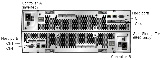
Throughout this section, illustrations show connections for the Sun StorageTek 6130 array. When connecting the Sun StorageTek 6540 array, you will use the controller ports with the same nomenclature; however, the ports appear in a different location on the Sun StorageTek 6540 array, as shown in FIGURE 5-1.
The Gateway system requires software release 4.20 (minimum) for gateway support.
The Sun StorageTek 6540 array requires the minimum software and firmware versions listed in TABLE 5-2.
Throughout this section, illustrations show connections for the Sun StorageTek 6130 array. When connecting the Sun StorageTek 6140 array, you will use the controller ports with the same nomenclature; however, the ports appear in a different location on the Sun StorageTek 6140 array, as shown in FIGURE 5-2.
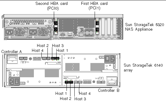
The following direct attach configurations are described in this section:
|
Note - Do not power on the server until instructed in Powering On the Gateway System. |
|
|
You can connect to SAN storage with one pair of optical fiber cables.
1. Connect the HBA Port 1 of the first HBA card (PCI1) to the Controller A host 1 port on the Sun StorageTek 6130/6140/6540 array.
2. Connect the HBA Port 1 of the second HBA card (PCI0) to the Controller B host 1 port on the Sun StorageTek 6130/6140/6540 array.
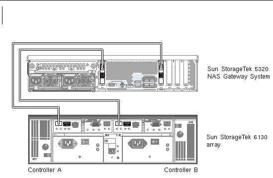
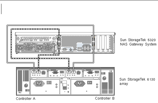
3. (Optional) For additional redundancy, attach the additional HBA ports.
a. Connect the HBA Port 2 of the first HBA card to the Controller B host 2 port on the Sun StorageTek 6130/6140/6540 array.
b. Connect the HBA Port 2 of the second HBA card to the Controller A host 2 port on the Sun StorageTek 6130/6140/6540 array.
|
|
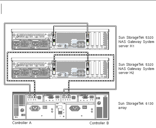
You can connect a dual-server high-availability (HA) Sun StorageTek 5320 NAS Cluster Gateway System to SAN storage with two optical fiber cables from each server.
|
Note - Each head must have two Fibre Channel connections to a SAN storage unit. One Fibre connection is insufficient for proper HA functionality. |
1. Connect the HBA Port 1 of the first HBA card (PCI1) on server H1 to the Controller A host 1 port on the Sun StorageTek 6130/6140/6540 array.
2. Connect the HBA Port 1 of the second HBA card (PCI0) on server H1 to the Controller B host 1 port on the Sun StorageTek 6130/6140/6540 array.
3. Connect the HBA Port 1 of the first HBA card on server H2 to the Controller A host 2 port on the Sun StorageTek 6130/6140/6540 array.
4. Connect the HBA Port 1 of the second HBA card on server H2 to the Controller B host 2 port on the Sun StorageTek 6130/6140/6540 array.
The following fabric attach configurations are described in this section:
|
Note - Do not power on the server until instructed in Powering On the Gateway System. |
Configure zoning of the FC switch so that a single host bus adapter (HBA) can access only one port (often referred to as "one-to-one" zoning). When necessary, you can also configure "overlapping" zones. Refer to your fabric switch documentation for additional information about zoning configuration.
|
|
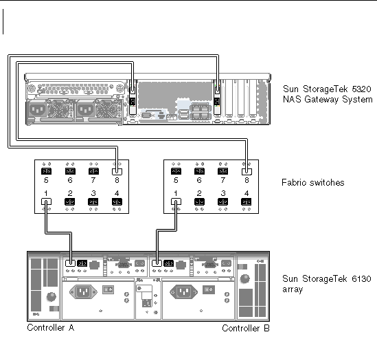
You can connect to SAN storage with one or two pairs of optical fiber cables. Using two pairs to connect all HBA ports and using two switches ensures redundancy and improves processing speed.
In the following illustration, port zones are shaded to indicate unique zones.
1. Connect the HBA Port 1 of the first HBA card (PCI1) to the first available port of the first fabric switch.
2. Connect the HBA Port 1 of the second HBA card (PCI0) to the first available port of the second fabric switch.
3. Connect an available port on the first switch to the Controller A host 1 port on the Sun StorageTek 6130/6140/6540 array.
4. Connect an available port on the second switch to the Controller B host 1 port on the Sun StorageTek 6130/6140/6540 array.
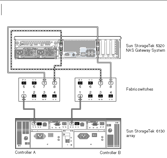
5. (Optional) For additional redundancy, attach the additional HBA ports:
a. Connect the HBA Port 2 of the first HBA card to the next available port of the second fabric switch.
b. Connect the HBA Port 2 of the second HBA card to the next available port of the first fabric switch.
|
|
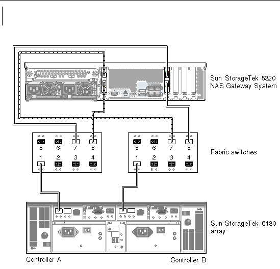
To enable all LUNs to be shared between all port pairs, attach the four HBA ports to two switches and use four cables to attach the switches to the Sun StorageTek 6130/6140 array:
1. Connect the HBA Port 1 of the first HBA card (PCI1) to the first available port of the first fabric switch.
2. Connect the HBA Port 1 of the second HBA card (PCI0) to the first available port of the second fabric switch.
3. Connect the HBA Port 2 of the first HBA card to the next available port of the second fabric switch.
4. Connect the HBA Port 2 of the second HBA card to the next available port of the first fabric switch.
5. Connect an available port on the first switch to the Controller A host 1 port on the Sun StorageTek 6130/6140 array.
6. Connect an available port on the second switch to the Controller B host 1 port on the Sun StorageTek 6130/6140 array.
|
|
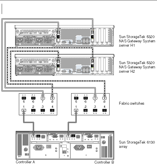
You can connect a dual-server high-availability Sun StorageTek 5320 NAS Cluster Gateway System to SAN storage with two or four pairs of optical fiber cables, with or without additional switch connections. Using four pairs to connect all HBA ports ensures redundancy and improves processing speed.
1. Connect the HBA Port 1 of the first HBA card (PCI1) in the server H1 to the first available port of the first fabric switch.
2. Connect the HBA Port 1 of the second HBA card (PCI0) in the server H1 to the first available port of the second fabric switch.
3. Connect the HBA Port 1 of the first HBA card in the server H2 to the next available port of the first fabric switch.
4. Connect the HBA Port 1 of the second HBA card in the server H2 to the next available port of the second fabric switch.
5. Connect an available port on the first switch to the Controller A host 1 port on the Sun StorageTek 6130/6140/6540 array.
6. Connect an available port on the second switch to the Controller B host 1 port on the Sun StorageTek 6130/6140/6540 array.
This section describes how to cable the Sun StorageTek 5320 NAS Gateway System directly or through fabric switches to the Sun StorageTek FlexLine 200 and 300 series systems:
After connecting the systems, proceed to Connecting to the Network.
|
Note - All figures in this section show the FlexLine 380 system. Cabling for the FlexLine 240 and FlexLine 280 is similar to the 380. |
You can direct connect a single server or a dual server to the Sun StorageTek FlexLine series array.
|
|
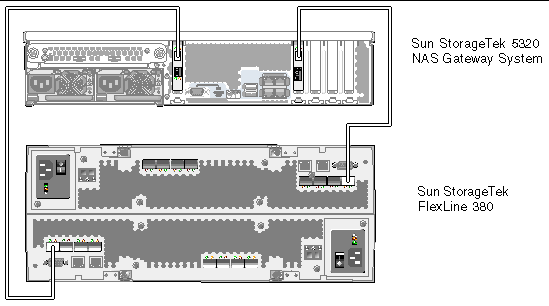
You can connect to SAN storage with one or two pairs of optical fiber cables. Using two pairs to connect all HBA ports ensures redundancy and improves processing speed.
1. Connect the HBA Port 1 of the first HBA card (PCI1) to the first available port on the Sun StorageTek FlexLine 200 and 300 series.
2. Connect the HBA Port 1 of the second HBA card (PCI0) to the next available port on the Sun StorageTek FlexLine 380 system.
|
|
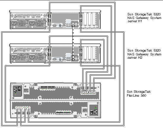
You can connect a dual-server high-availability (HA) Sun StorageTek 5320 NAS Cluster Gateway System to SAN storage with two or four pairs of optical fiber cables. Using four pairs to connect all HBA ports simulates a dual array, ensures redundancy, and improves processing speed.
1. Connect the HBA Port 1 of the first HBA card (PCI1) on server H1 to the first available port on the Sun StorageTek FlexLine 200 and 300 series.
2. Connect the HBA Port 1 of the second HBA card (PCI0) on server H1 to the next available port on the Sun StorageTek FlexLine 200 and 300 series.
3. Connect the HBA Port 1 of the first HBA card on server H2 to the next available port on the Sun StorageTek FlexLine 200 and 300 series.
4. Connect the HBA Port 1 of the second HBA card on server H2 to the next available port on the Sun StorageTek FlexLine 200 and 300 series.
The following fabric attach configurations are described in this section:
|
Note - Do not power on the server until instructed in Powering On the Gateway System. |
Configure zoning of the FC switch so that a single host bus adapter (HBA) can access only one port (often referred to as "one-to-one" zoning). When necessary, you can also configure "overlapping" zones. Refer to your fabric switch documentation for additional information about zoning configuration.
|
|
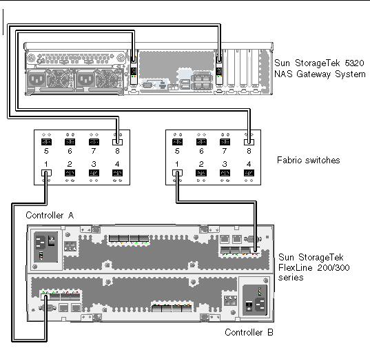
You can connect to SAN storage with one or two pairs of optical fiber cables. Using two pairs to connect all HBA ports and using two switches ensures redundancy and improves processing speed.
1. Connect the HBA Port 1 of the first HBA card (PCI1) to the first available port of the first fabric switch.
2. Connect the HBA Port 1 of the second HBA card (PCI0) to the first available port of the second fabric switch.
3. Connect an available port on the first switch to the Controller A host 1 port on the Sun StorageTek FlexLine 200 and 300 series.
4. Connect an available port on the second switch to the Controller B host 1 port on the Sun StorageTek FlexLine 200 and 300 series.
|
|
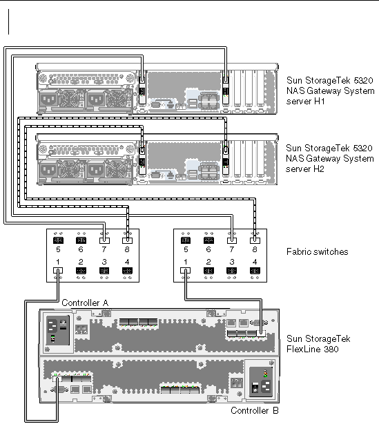
You can connect a dual-server high-availability Sun StorageTek 5320 NAS Cluster Gateway System to SAN storage with two or four pairs of optical fiber cables, with or without additional switch connections. Using four pairs to connect all HBA ports ensures redundancy and improves processing speed.
1. Connect the HBA Port 1 of the first HBA card (PCI1) in the server H1 to the first available port of the first fabric switch.
2. Connect the HBA Port 1 of the second HBA card (PCI0) in the server H1 to the first available port of the second fabric switch.
3. Connect the HBA Port 1 of the first HBA card in the server H2 to the next available port of the first fabric switch.
4. Connect the HBA Port 1 of the second HBA card in the server H2 to the next available port of the second fabric switch.
5. Connect an available port on the first switch to the Controller A host 1 port on the Sun StorageTek FlexLine 200 and 300 series.
6. Connect an available port on the second switch to the Controller B host 1 port on the Sun StorageTek FlexLine 200 and 300 series.
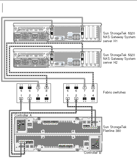
7. (Optional) For additional redundancy, attach additional cables from the two switches:
a. Connect the next available port on the first switch to the Controller B host 2 port on the Sun StorageTek FlexLine 200 and 300 series.
b. Connect the next available port on the second switch to the Controller A host 2 port on the Sun StorageTek FlexLine 200 and 300 series.
To use the Sun StorageTek FlexLine 200 and 300 series array for Sun StorageTek 5320 NAS Gateway System storage, the host type parameter of both controller A and controller B on the FlexLine series array must be set to SE_5xxx. The SE_5xxx host type option is available on the FlexLine series array only if it is running NVSRAM version N6091-616843-005 or later.
If the FlexLine series array is not running this version of NVSRAM, you need to either upgrade to this NVSRAM version or run two scripts to add the NAS host type region.
The two scripts (CtrlAModReg12 and CtrlBModReg12) are available in patch number 124128-01 on http://sunsolve.sun.com. The two scripts are available in patch number 124128-01 on http://sunsolve.sun.com. You must have a valid service contract in order to access the patch.
|
Note - If you are running NVSRAM N6091-616843-005, you do not need to perform this procedure. |
1. Verify that host type region 12 is not in use by opening the SANtricity Storage Manager and go to Storage System > View > Profile > Mappings. If host type region 12 is already in use by a valid host type, you need to modify the scripts. See Changing the Host Type Region on the Scripts for more information.
2. Select the Patchfinder link on http://sunsolve.sun.com, and enter patch number 124128-01 to download the patch.
3. Extract the scripts CtrlAModReg12 and CtrlBModReg12 from the patch.
4. Run the script CtrlAModRegion12 to update the host type parameter on controller A:
# SMcli IP_address_controller_A -f CtlrAModRegion12
5. Run the script CrtlBModRegion12 to update the host type parameter on controller B:
6. # SMcli IP_address_controller_B -f CtrlBModRegion12Reset controller A:
# SMcli IP_address_controller_A -c "reset controller [a];"
# SMcli IP_address_controller_B -c "reset controller [b];"
8. Verify that the host type has been changed to SE_5xxx by opening the SANtricity Storage Manager and go to Storage System > View > Profile > Mappings.
Do not upgrade to NVSRAM N6091-616843-005 if host type region 12 is already in use. If the host type region 12 is currently in use, you need to modify the scripts before running them.
To edit the scripts to change the host type region:
1. Download the patch as described in Step 2 of the previous procedure.
2. Open the scripts CtrlAModReg12 and CtrlBModReg12 in the SMcli.
3. Replace the index number of 12 with the index number of the host type region you need to modify.
4. Continue with step 3 in Modifying the Host Type on the Sun StorageTek FlexLine 200 and 300 Series Array.
This section describes how to cable the Sun StorageTek 5320 NAS Gateway System directly or through fabric switches to the Sun StorEdge 6920 system:
After connecting the systems, proceed to Connecting to the Network.
The following direct attach configurations are described in this section:
|
Note - Do not power on the server until instructed in Powering On the Gateway System. |
|
|
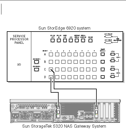
You can connect to SAN storage with one or two pairs of optical fiber cables. Using two pairs to connect all HBA ports ensures redundancy and improves processing speed.
1. Connect the HBA Port 1 of the first HBA card (PCI1) to the first available port on the Sun StorEdge 6920 system.
2. Connect the HBA Port 1 of the second HBA card (PCI0) to the next available port on the Sun StorEdge 6920 system.
|
|
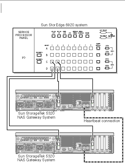
You can connect a dual-server high-availability (HA) Sun StorageTek 5320 NAS Cluster Gateway System to SAN storage with two or four pairs of optical fiber cables. Using four pairs to connect all HBA ports simulates a dual array, ensures redundancy, and improves processing speed.
1. Connect the HBA Port 1 of the first HBA card (PCI1) on server H1 to the first available port on the Sun StorEdge 6920 system.
2. Connect the HBA Port 1 of the second HBA card (PCI0) on server H1 to the next available port on the Sun StorEdge 6920 system.
3. Connect the HBA Port 1 of the first HBA card on server H2 to the next available port on the Sun StorEdge 6920 system.
4. Connect the HBA Port 1 of the second HBA card on server H2 to the next available port on the Sun StorEdge 6920 system.
The following fabric attach configurations are described in this section:
|
Note - Do not power on the server until instructed in Powering On the Gateway System. |
|
|
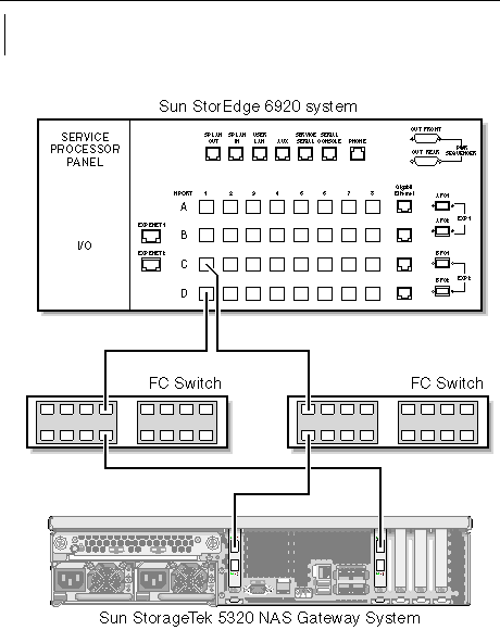
You can connect to SAN storage with one or two pairs of optical fiber cables. Using two pairs to connect all HBA ports and using two switches ensures redundancy and improves processing speed.
1. Connect the HBA Port 1 of the first HBA card (PCI1) to the first available port of the first fabric switch.
2. Connect the HBA Port 1 of the second HBA card (PCI0) to the first available port of the second fabric switch.
3. Connect an available port on the first switch to the first available port on the Sun StorEdge 6920 system.
4. Connect an available port on the second switch to the next available port on the Sun StorEdge 6920 system.
|
|
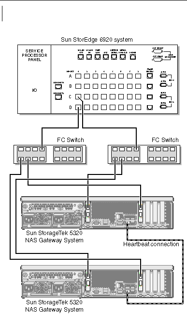
You can connect a dual-server high-availability Sun StorageTek 5320 NAS Cluster Gateway System to SAN storage with two or four pairs of optical fiber cables, with or without additional switch connections. Using four pairs to connect all HBA ports ensures redundancy and improves processing speed.
1. Connect the HBA Port 1 of the first HBA card (PCI1) in the server H1 to the first available port of the first fabric switch.
2. Connect the HBA Port 1 of the second HBA card (PCI0) in the server H1 to the first available port of the second fabric switch.
3. Connect the HBA Port 1 of the first HBA card in the server H2 to the next available port of the first fabric switch.
4. Connect the HBA Port 1 of the second HBA card in the server H2 to the next available port of the second fabric switch.
5. Connect an available port on the first switch to the first available port on the Sun StorEdge 6920 system.
6. Connect an available port on the second switch to the next available port on the Sun StorEdge 6920 system.
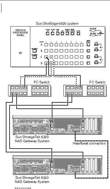
7. (Optional) To enable all LUNs to be shared between all port pairs, attach additional cables from the two switches:
a. Connect the next available port on the first switch to the next available port on the Sun StorEdge 6920 system.
b. Connect the next available port on the second switch to the next available port on the Sun StorEdge 6920 system.
This section describes how to cable the Sun StorageTek 5320 NAS Gateway System or NAS Gateway Cluster System directly or through fabric switches to the Sun StorEdge 99xx system:
After connecting the systems, proceed to Connecting to the Network.
The following direct attach configurations are described in this section:
|
Note - Do not power on the server until instructed in Powering On the Gateway System. |
|
|
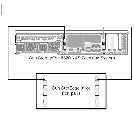
You can connect to SAN storage with one or two pairs of optical fiber cables. Using two pairs to connect all HBA ports ensures redundancy and improves processing speed.
1. Connect the HBA Port 1 of the first HBA card (PCI1) to the first available port on the Sun StorEdge 99xx system.
2. Connect the HBA Port 1 of the second HBA card (PCI0) to the next available port on the Sun StorEdge 99xx system.
|
|
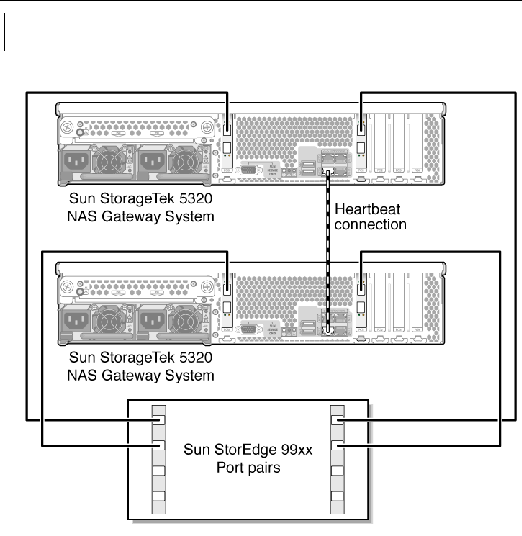
You can connect a dual-server high-availability (HA) Sun StorageTek 5320 NAS Cluster Gateway System to SAN storage with two or four pairs of optical fiber cables. Using four pairs to connect all HBA ports simulates a dual array, ensures redundancy, and improves processing speed.
1. Connect the HBA Port 1 of the first HBA card (PCI1) on server H1 to the first available port on the Sun StorEdge 99xx system.
2. Connect the HBA Port 1 of the second HBA card (PCI0) on server H1 to the next available port on the Sun StorEdge 99xx system.
3. Connect the HBA Port 1 of the first HBA card on server H2 to the next available port on the Sun StorEdge 99xx system.Connect the HBA Port 1 of the second HBA card on server H2 to the next available port on the Sun StorEdge 99xx system.
The following fabric attach configurations are described in this section:
|
Note - Do not power on the server until instructed in Powering On the Gateway System. |
|
|
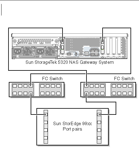
You can connect to SAN storage with one or two pairs of optical fiber cables. Using two pairs to connect all HBA ports and using two switches ensures redundancy and improves processing speed.
1. Connect the HBA Port 1 of the first HBA card (PCI1) to the first available port of the first fabric switch.
2. Connect the HBA Port 1 of the second HBA card (PCI0) to the first available port of the second fabric switch.
3. Connect an available port on the first switch to the first available port on the Sun StorEdge 99xx system.
4. Connect an available port on the second switch to the next available port on the Sun StorEdge 99xx system.
|
|
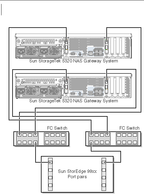
You can connect two independent (not high-availability) Sun StorageTek 5320 NAS Gateway System servers.
1. Connect the HBA Port 1 of the first HBA card (PCI1) in the first server to the first available port of the first fabric switch.
2. Connect the HBA Port 1 of the second HBA card (PCI0) in the first server to the first available port of the second fabric switch.
3. Connect the HBA Port 1 of the first HBA card in the second server to the next available port of the first fabric switch.
4. Connect the HBA Port 1 of the second HBA card in the second server to the next available port of the second fabric switch.
5. Connect an available port on the first switch to the first available port on the Sun StorEdge 99xx system.
6. Connect an available port on the second switch to the next available port on the Sun StorEdge 99xx system.
|
|
You can connect a dual-server high-availability Sun StorageTek 5320 NAS Cluster Gateway System to SAN storage with two or four pairs of optical fiber cables, with or without additional switch connections. Using four pairs to connect all HBA ports ensures redundancy and improves processing speed.
1. Connect the HBA Port 1 of the first HBA card (PCI1) in the server H1 to the first available port of the first fabric switch.
2. Connect the HBA Port 1 of the second HBA card (PCI0) in the server H1 to the first available port of the second fabric switch.
3. Connect the HBA Port 1 of the first HBA card in the server H2 to the next available port of the first fabric switch.
4. Connect the HBA Port 1 of the second HBA card in the server H2 to the next available port of the second fabric switch.
5. Connect an available port on the first switch to the first available port on the Sun StorEdge 99xx system.
6. Connect an available port on the second switch to the next available port on the Sun StorEdge 99xx system.
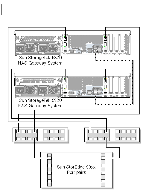
7. (Optional) To enable all LUNs to be shared between all port pairs, attach additional cables from the two switches:
a. Connect the next available port on the first switch to the next available port on the Sun StorEdge 99xx system.
b. Connect the next available port on the second switch to the next available port on the Sun StorEdge 99xx system.
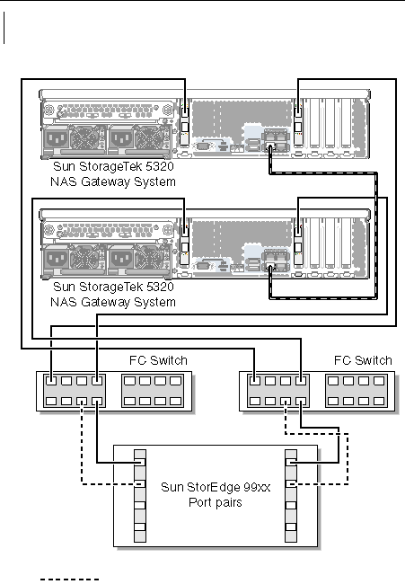
The Sun StorageTek 5320 NAS Gateway System network connections depend on your system configuration. Each configuration is described in this section.
The available network connectors depend on your system configuration: Fast Ethernet or optical Gigabit Ethernet (optional card installation required).
|
|
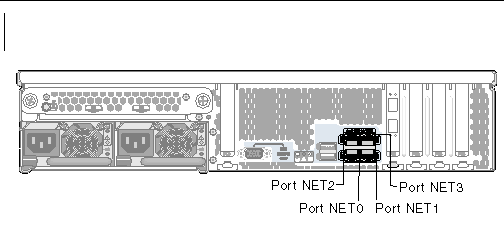
 Connect an RJ-45 unshielded twisted-pair cable from your local area network (LAN) to the port NET0 or the port NET1 on the back of the Sun StorageTek 5320 NAS Gateway System.
|
Note - Later, when you configure the system (see Initial Gateway System Single-Server Configuration), the NET0 port is displayed as "Port emc1" and the NET1 port is displayed as "Port emc2." |
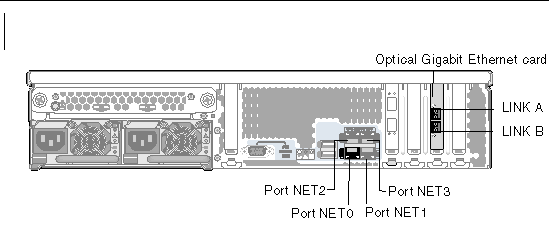
 Connect an optical network cable to the top (LINK A) optical gigibit Ethernet connector and another optical network cable to the bottom (LINK B) optical Gigabit Ethernet connector on the back of the Sun StorageTek 5320 NAS Gateway System.
|
Note - Later, when you configure the system (see Initial Gateway System Single-Server Configuration), the LINK A port displays as "Port emf3" and the LINK B port displays as "Port emf4." |
Each server in a dual-server Sun StorageTek 5320 NAS Cluster Gateway System uses a dedicated Ethernet connection to communicate with its partner and perform periodic "health checks." The port used for the health check connection is referred to as the heartbeat port. The NET0 Gigabit Ethernet port is used for the heartbeat.
The dual-server Sun StorageTek 5320 NAS Cluster Gateway System is commonly configured with four on-board copper gigabit ports and two dual-port Gigabit Ethernet cards (FIGURE 5-28).
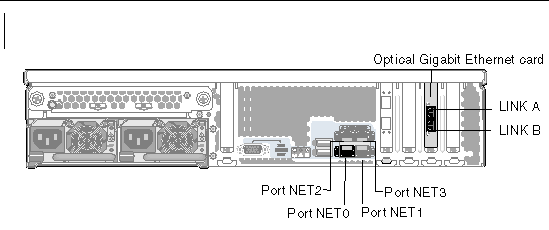
 Use an RJ-45 unshielded twisted-pair cable to connect the two servers' NET0 heartbeat ports.
 Connect a Cat5 (for a 100BASE-T network) or Cat5e (for a 1000BASE-T network) Ethernet cable from your LAN to the NIC NET1, NET2, or NET3 port on the back of each of the servers (see FIGURE 5-28 for NIC port locations).
 Connect an optical network cable from the network to the top (LINK A) and connect another optical network cable from the network to the bottom (LINK B) optical Gigabit Ethernet connector on the back of each of the servers (see FIGURE 5-28 for NIC and optical Gigabit Ethernet port locations).
Before you proceed with initializing the system, you must power on the Sun StorageTek 5320 NAS Gateway System or NAS Gateway Cluster System.
|
1. Verify that all cables between the Sun StorageTek 5320 NAS Gateway System and SAN storage have been connected.
Refer to Connecting the Sun StorageTek 5320 NAS Gateway System to the Sun StorageTek 6130/6140/6540 Array, Connecting the Sun StorageTek 5320 NAS Gateway System to the Sun StorEdge 6920 System, or Connecting the Gateway System or Gateway Cluster System to the Sun StorEdge 99xx System.
2. Verify that the Sun StorageTek 5320 NAS Gateway System is connected to the network.
Refer to Connecting to the Network.
3. For the Sun StorageTek 5320 NAS Cluster Gateway System dual-server configuration, verify that the health-monitoring cable is connected.
Refer to To Connect the Health-Monitoring Cable.
4. Using a pen tip or similar implement, press the recessed Power button (FIGURE 5-29).
For the Sun StorageTek 5320 NAS Cluster Gateway System dual-server configuration, power on both servers.
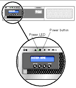
5. Wait for the system to boot up and display the menu on the LCD panel.
The NIC, System Status, and System ID LEDs should be green. On the back of the server, the link lights for the HBA ports should be green.
6. Proceed to the appropriate initial configuration instructions.
For the Sun StorageTek 5320 NAS Gateway System single-server configuration, refer to Initial Gateway System Single-Server Configuration.
For the Sun StorageTek 5320 NAS Cluster Gateway System configuration, refer to Initial Cluster Gateway System Configuration.
|
Note - These instructions apply to the Sun StorageTek 5320 NAS Gateway System single server only. For Sun StorageTek 5320 NAS Cluster Gateway System configuration instructions, refer to Initial Cluster Gateway System Configuration. For Sun StorageTek 5320 NAS Appliance configuration instructions, refer to Chapter 3. |
To complete the initial Sun StorageTek 5320 NAS Gateway System configuration, you must specify the following:
|
If your network supports DHCP, an IP address is automatically assigned to your LAN port.
If DHCP is not available or you want to assign a static IP address, use the server's LCD panel:
3. Select A. Set Gateway and enter the gateway address.
To enter data, use the up and down arrow buttons to select digits, dots, or spaces. Then use the ENTER or right arrow button to accept each character.
4. Select C. Set Port-emx1 or C. Set Port-emx2 (depending on which port is the first regular LAN port) and enter the IP address, subnet mask, and broadcast address as prompted.
This IP address information is assigned to the first regular LAN port on your system.
5. Select Escape twice to return to the main menu.
To configure the system, you must set up basic system configuration and activate the license for the server.
|
Note - You must perform both tasks before proceeding to SAN Storage Configuration. |
1. From a client on the same network, open a Java platform-enabled web browser with Java Plug-in and enter the IP address for the server.
2. Accept the "Applet Security Certificate" and wait until the Web Admin applet is loaded on this system.
3. On the Web Admin login screen, click Apply.
The password can be set later. Refer to the Sun StorageTek 5320 NAS OS Administration Guide.
4. On the Set Time and Date panel, select the date, the time, and the time zone, and click Apply. Then click Yes to confirm.
This sets the secure clock to the same time and date. Make sure you set the time and date accurately as you can set the secure clock only once.
5. Read the license agreement in the Configuration wizard dialog box, and click Accept to proceed with the following wizard steps:
a. Click Next in the Welcome dialog box.
b. From the Select Environment screen, configure Microsoft Windows, UNIX, or both environments, and click Next to continue.
c. From the Set Server Name screen, type the server name and populate the other fields accordingly, and then click Next.
d. On the Configure Network Adapters screen, verify that the information is correct, and click Next to continue.
You can configure additional network interfaces at this time. However, if you change the configuration of the port to which the browser is attached, the browser session is disconnected.
e. On the Set Gateway Address screen, verify that the address is correct, and, if not, type the gateway address. Click Next to continue.
f. If you are configuring a Windows environment:
i. Select Domain or Workgroup. To configure a Domain, type the name of the Windows 2000 domain where ADS is running, the user name, and password.
ii. Select Enable ADS to enable Active Directory Service (ADS). In the Container field, type the ADS path location of the Windows user.
|
Note - Click the Help button if you need information about the fields on the Configure Domains and Workgroups screen. |
iv. To set up Windows Internet Naming Service (WINS), click Enable WINS on the Set Up WINS screen. If you need information about the fields on the Set Up WINS screen, click the Help button.
g. On the Set Up DNS screen, click Enable DNS to set up the Domain Name Service (DNS). Click the Help button for information about the fields on this screen. Click Next to continue.
|
Note - When adding your DNS server, click Add item to list to ensure that the DNS server has been added. |
h. If you are configuring a UNIX environment, set up name services (NIS, NIS+, and NSSLDAP). Click the Help button for information about the fields on this screen. After filling in this screen, click Next to continue.
i. On the Set Up Email Notification screen, enter the Simple Mail Transport Protocol (SMTP) server name and specify the recipients who should receive system notifications and warnings. Click Next to continue.
j. On the Set Up Logging screen, to enable remote or local logging. Click Help for information about the fields on this screen. After filling in this screen, click Next to continue.
k. On the Set Time and Date screen, set the server date and time. Click Next to continue.
l. On the Assign Language screen, specify the language to display by the Web Admin application. Click Next to continue.
m. On the Online System Registration screen, choose to register now or later. If you choose to register now complete the following:
a. Check the Agree box to agree to the terms in the Disclaimer box.
b. On the Sun Account tab, enter your Sun Account ID and password.
c. On the Proxy Server tab, enter your HTTP proxy server name and port number, Proxy User Name, and Proxy User Password.
d. On the Options tab, select Sent Heartbeat Data and/or Send Fault Events to send this data as part of the phone home information.
n. In the Confirmation screen, review the configuration information you have added.
|
Note - Be sure the configuration information is accurate before continuing. |
o. Click Finish on the wizard Confirmation screen.
The system configures the settings and indicates that in the Save Configuration screen. It also displays a message that both servers must reboot for the failover changes to be applied.
p. Click Close on the Save Configuration screen.
1. In the navigation panel, select System Operations > Activate Options.
2. Click the Temporary Licenses button.
3. Select Sun StorageTek NAS Gateway, and click Apply.
The State displays "valid" and the Status displays "active."
4. Log out of Web Admin, and close all browser instances.
|
Note - You must close all browser windows you have open. If you don't, the license feature will not set up properly. |
5. Restart the Web Admin using Step 1 through Step 3 in To Set Up Basic Configuration.
6. When you have logged in to Web Admin, on the main System Status window, check the Features Enabled to be sure that "Sun StorageTek NAS Gateway" appears.
7. In the navigation panel, select RAID > View HBA Information to view the port World Wide Names (WWNs) of the HBA ports.
Each HBA port is delineated by a tab at the top of the window. HBA port numbering refers to the physical HBA ports from right to left and bottom to top, as shown in TABLE 5-3.
|
Note - If a third HBA card is installed to allow tape backup, then the data ports will be 1, 2, 5, and 6. |
For each HBA port, the port WWN is listed in the upper portion of the window. The port WWNs are used to map the LUNs on the SAN storage device or to zone these ports on the fabric switch.
8. Write down the port WWNs of all the HBA ports.
WWNs consist of 16 characters that start after the "x" and do not include the "."
9. Log out of Web Admin and close the browser.
10. Configure SAN storage using the appropriate instructions:
11. Configure storage on the Sun StorageTek 5320 NAS Gateway System using the instructions in the next section.
|
|
1. Reboot the Sun StorageTek 5320 NAS Gateway System server so that it can detect the storage.
You can reboot using Web Admin or the LCD panel.
a. In the navigation panel, select System Operations > Shut Down the Server.
b. Select Reboot This Head, and click Apply.
To use the LCD panel to reboot:
a. On the server's LCD panel, select B. Shutdown Server from the menu.
b. Select B. Reboot. The LCD displays "Are you sure? No." Press the up arrow button to change to "Yes." Then press the ENTER or the right arrow button to reboot.
2. After the server has rebooted, use Web Admin to configure file volumes.
3. From the navigation panel, choose File Volume Operations > Create File Volumes to create a volume. 
4. Select the logical unit number (LUN) on which you want to create the volume. Enter a name and size for the volume. Select a partition (if available) on which you want to create the volume and select the volume type.
For more information about the fields, legends, and buttons on this panel, click the Help button.
5. Click Apply to create the new volume.
|
Note - These instructions apply to the Sun StorageTek 5320 NAS Cluster Gateway System configuration only. For Sun StorageTek 5320 NAS Gateway System configuration instructions, refer to Initial Gateway System Single-Server Configuration. For Sun StorageTek 5320 NAS Cluster Appliance configuration instructions, refer to Chapter 4. |
To complete the initial Sun StorageTek 5320 NAS Cluster Gateway System configuration, you must specify the following:
|
If your network supports DHCP, an IP address is automatically assigned to your LAN ports.
If DHCP is not available or you want to assign a static IP address, use server H1's LCD panel:
3. Select A. Set Gateway and enter the gateway address.
To enter data, use the up and down arrows to select digits, dots, or spaces. Then use the ENTER or right arrow button to accept each character.
4. Select C. Set Port-emc2 (or emc3 or emc4) and enter the IP address, subnet mask, and broadcast address as prompted.
This IP address information is assigned to the first regular (non-heartbeat) LAN port on your system.
5. Select Escape twice to return to the main menu.

|
Caution - Do not change the private IP address on the network port that is used for the HB port (heartbeat port), emc1. |
|
Note - If you would like to verify your settings on the LCD panel, HB Port shows a private IP address, and Port emc2 or Port emc3 or Port emc4 shows the information you just entered. |
You can edit the port information and assign addresses to other ports in the same way.
To configure the system, you must set up basic system configuration and activate the license for server H1, and then repeat the steps for server H2.
|
Note - You must perform all basic system configuration tasks on both servers before proceeding to To Configure LUN Paths. |
1. From a client on the same network, open a Java platform-enabled web browser with Java Plug-in and type the IP address for server H1.
2. Accept the "Applet Security Certificate" and wait until the Web Admin applet is loaded on this system.
3. On the Web Admin login screen, click Apply.
The password can be set later. Refer to the Sun StorageTek 5320 NAS OS Administration Guide.
4. On the Set Time and Date panel, select the date, the time, and the time zone, and click Apply. Then click Yes to confirm.
This sets the secure clock to the same time and date. Make sure you set the time and date accurately as you can set the secure clock only once.
5. Read the license agreement in the Configuration wizard dialog box, and click Accept to proceed with the following wizard steps:
a. Click Next in the Welcome dialog box.
b. From the Select Environment screen, configure Microsoft Windows, UNIX, or both environments. Click Next to continue.
You can add additional configuration information later.
c. From the Set Server Name screen, type the server name and populate the other fields accordingly, and then click Next.
d. On the Enable Failover screen, skip the screen by clicking Next.

|
Caution - Do not enable failover at this time. Storage must be configured before failover can be enabled. |
In the partner configuration part of the screen, the system initially sets default server names head1 and head2. You can change these defaults later when you configure failover (see To Configure Failover).
e. On the Configure Network Adapters screen, verify that the information is correct, and click Next to continue.
You can configure additional network interfaces at this time. However, if you change the configuration of the port to which the browser is attached, the browser session is disconnected.
f. On the Set Gateway Address screen, verify that the address is correct, and, if not, enter the gateway address. Click Next to continue.
g. For all the other wizard configuration steps, refer to the Sun StorageTek 5320 NAS OS Administration Guide for more information.
|
Note - When adding your DNS server, click Add to ensure the DNS server has been added. |
h. In the Confirmation screen, review the configuration information you have added.
|
Note - Be sure the configuration information is accurate before continuing. |
i. Click Finish on the wizard Confirmation screen.
The system configures the settings and indicates that in the Save Configuration screen.
j. Click Close on the Save Configuration screen.
1. In the navigation panel, select System Operations > Activate Options.
2. Click the Temporary Licenses button.
3. Select Sun StorageTek NAS Gateway, and click Apply.
The State displays "valid" and the Status displays "active."
4. Log out of Web Admin, and close all browser instances.
|
Note - You must close all browser windows you have open. If you don't, the license feature will not set up properly. |
5. Restart Web Admin using Step 1 through Step 3 in Basic Dual-Server System Configuration.
6. When you have logged in to Web Admin, on the main System Status window, check the Features Enabled to be sure that "Sun StorageTek NAS Gateway" appears.
7. In the navigation panel, select RAID > View HBA Information to view the port World Wide Names (WWNs) of the HBA ports.
The port WWNs are used to map the LUNs on the SAN storage device or to zone these ports on the fabric switch.
Each HBA port is delineated by a tab at the top of the window. HBA port numbering refers to the physical HBA ports from right to left and bottom to top. Refer to TABLE 5-3, HBA Port Numbering.
For each HBA port, the port WWN is listed in the upper portion of the window. The port WWNs are used to map the LUNs on the SAN storage device or to zone these ports on the fabric switch.
8. Write down the port WWNs of all the HBA ports.
WWNs consist of 16 characters that start after the "x" and do not include the "."
9. Log out of Web Admin and close the browser.
1. Assign server H2's IP address and gateway address using the instructions in To Set IP Addresses.
2. Set up server H2's basic configuration using the instructions in To Set Up Basic Configuration.
3. Activate server H2's license using the instructions To Activate the Sun StorageTek NAS Gateway License.
1. Configure SAN storage using the appropriate instructions:
2. Configure storage on the Sun StorageTek 5320 NAS Cluster Gateway System, using the instructions in the next section.
1. Power off server H1 and H2 using Web Admin or the LCD panel:
3. When server H1 has restarted and the LCD panel displays QUIET, press the ENTER or right arrow button. Then press the down arrow button until the flashing cursor is on C. Take All LUNs.
4. Press the ENTER or right arrow button to select C. Take All LUNs.
5. When prompted to "Take All LUNs? No," press the up arrow button to select "Yes," and press the ENTER or right arrow button to start taking LUNs.
The LCD displays "Taking LUNs" followed by a message "Took n LUNs." After a few seconds, the display returns to the Network Config menu.
6. Select Escape to return to the main menu.
Server H1 is now in the ALONE state.
1. Launch a new browser window and enter server H1's IP address.
2. If necessary, accept the "Applet Security Certificate" and wait until the Web Admin applet is loaded.
3. On the Web Admin login screen, click Apply.
4. In the navigation panel, select High Availability > Recover.
5. In the Current RAID Configuration and Restore RAID Configuration panels, confirm that all the LUNs are listed in the Head 1 columns.
There is nothing listed under any Head 2 column.
6. In the navigation panel, select High Availability > Enable Failover.
7. Select Automatic Failover and Enable Link Failover.
A default value of 60 seconds is assigned in both the Down Timeout and Restore Timeout fields.
8. Type the Partner Configuration Name and the Gateway IP address for server H2 (Partner Name factory default is "head2"), using the Tab key to move between fields.
The information you enter here is used to start server H2 through the heartbeat connection. The Partner Name is the host name that you assigned to server H2. Any network information server H2 obtained through DHCP or manually through the LCD panel is displayed here and can be corrected, if necessary.
The field for Private IP for the heartbeat connection should already be populated (IP 10.10.10.2 private network) and should not be changed.
10. A message appears stating that the system will be rebooted for changes to take effect. Confirm that you want to reboot both servers.
Server H1 reboots automatically, and you need to manually restart server H2.
11. If server H2 is powered off, power it on. Otherwise, reboot server H2 in one of these ways:
12. When the servers have restarted, log in to the Web Admin on server H1.
13. In the main Server Status window, check that the Head Status is ALONE and the Partner Status is QUIET.
1. Using Web Admin on server H1, in the navigation panel, select High
Availability >Recover.
2. In the Restore RAID Configuration window, assign some of the LUNs to server H2.
|
Note - You must assign at least one LUN to each server. In most situations, you will want approximately equal amounts of storage assigned to each server in the cluster. |
|
Note - Verify that the Current RAID Configuration window shows the LUN assignments. |
4. Click Recover, and the LUNs are distributed between both the servers.
At this point, both servers change to the NORMAL state.
|
Note - Verify that both servers are in the NORMAL state on the LCD display or on the Web Admin main Server Status window, where the Head and Partner Status should display NORMAL. |
5. Follow these steps first on server H1 and then on server H2:
a. Using Web Admin on server H1, in the navigation panel, select Network Configuration > Configure TCP/IP > Configure Network Adapters.
b. Check that the emc or emf NIC port being used displays the partner IP alias address.
|
You need to assign LUN paths on each server to balance multipath access from each server to storage.
Follow these steps first on server H1 and then on server H2:
1. In the Web Admin navigation panel, select High Availability > Set LUN Path.
2. Select a LUN and click Edit.
3. Select the desired storage from the Primary Path drop-down menu.
Evenly divide the assignment of LUNs to the two available paths. For example, the first and third LUN to 1/0 and the second and fourth LUN to 1/1.
For additional information about LUNs and other detailed software setup and use, click Help or refer to the Sun StorageTek NAS OS Administration Guide.
To configure storage for the Sun StorageTek 5320 NAS Gateway System, you must first configure the SAN storage system and then finish configuration on the Sun StorageTek 5320 NAS Gateway System.
|
Note - You must perform all the storage and LUN configuration tasks to complete the initial configuration. |
If you are using fabric switches, use the switch user interface (UI) to include all WWNs of the SAN storage and of the HBAs on the Sun StorageTek 5320 NAS Gateway System.
To use the Sun StorageTek 6130 array for Sun StorageTek 5320 NAS Gateway System storage, there are certain requirements.
|
Note - Special configuration requirements do not apply to the Sun StorageTek 6140 array. Refer to Sun StorageTek 6140 Array for basic Sun StorageTek 6140 array configuration. |
The Sun StorageTek 6130 array requires the software and firmware shown in TABLE 5-4 to interoperate with the Gateway System.
If the Sun StorageTek 6130 array is currently at version 1.2, upgrade the management software to version 1.3 before installing the patches.
If the Sun StorageTek 6130 array is currently at version 1.3, install the patches as described in To Upgrade the Sun StorageTek 6130 Array Firmware.
|
|
1. From the Sun StorageTek 6130 array management interface, log in to the Sun Storage Automated Diagnostic Environment and clear all existing alarms.
2. Log in to the management host as root.
3. Download the latest Sun StorageTek 6130 host software package v1.3 for Solaris OS from http://sunsolve.sun.com to any working directory on the management host.
4. Unzip the distribution file and untar the file.
5. Enter the following command:
The -n option specifies a non-interactive upgrade. After asking whether you want to upgrade software or firmware, the script completes the upgrade without pausing for questions.
When the installation is complete, a confirmation is displayed followed by the date and time that the upgrade finished.
You can now install the patches as described in the next section.
1. Download the required patches (see TABLE 5-4) from http://sunsolve.sun.com/.
2. Stop all I/O to the disk drives.
3. Log in to the management host as root.
4. Change to the directory to which you downloaded the software.
5. Install each patch by following the instructions in the patch README file.
6. Verify that the latest patches are installed:
b. Enter the IP address of the management host using this format:
c. Log in to the management software.
d. Click Sun StorageTek 6130 Configuration Service.
The Array Summary page is displayed.
e. Verify that the Firmware Version column displays 06.12.09.10 (or greater).
To verify that the array is seen by the Sun StorageTek 6130 host software, use automatic discovery or manual registration.
If the array is on the same subnet as the management host, you can automatically verify the array.
2. Type the IP address of the management host using this format:
3. Log in to the management software.
4. Click Sun StorageTek 6130 Configuration Service.
The Array Summary page is displayed.
5. On the Array Summary page, click Auto Discover to display arrays that are on the same subnet as the management host.
|
Note - It takes approximately 2 minutes for the software to discover each array. |
6. Verify that the array is listed on the Array Summary page.
If the array is not on the same subnet as the management host, you must manually register the array.
2. Type the IP address of the management host using this format:
3. Log in to the management software.
4. Click Sun StorageTek 6130 Configuration Service.
The Array Summary page is displayed.
5. On the Array Summary page, click Register Array.
The Array Registration page is displayed.
6. Enter the IP address of the controller and click OK.
7. Verify that the array is listed on the Array Summary page.
To make the Sun StorageTek 6130 SAN storage available to the NAS Gateway system, do the following:
1. Create an initiator on the Sun StorageTek 6130 array.
2. Define a new volume on the Sun StorageTek 6130 array.
3. Create a NAS volume on the NAS server.
1. Log in to the Sun StorageTek 6130 Configuration Service software, and click Physical Storage. Initiators. The Initiator Summary page is displayed.
2. Click New. The New Initiator Summary page is displayed.
3. Enter a name for the new initiator, using a maximum of 30 characters.
4. Select an existing World Wide Name (WWN), or enter a new one.
5. Select the host for the new initiator.
6. Select SE_5xxx as the host type.
7. Click OK. The Initiator Summary page displays the initiator name, host name, host type, and WWN of the new initiator.
1. In the Sun StorageTek 6130 Configuration Service interface, click Logical Storage > Volumes. The Volume Summary page is displayed.
2. Click New. The New Volume wizard is displayed.
3. Enter a name and capacity for the volume.
4. Select the virtual disk you want to use for this volume.
5. Map the volume to the Sun StorageTek 5320 NAS Gateway host. The new volume is displayed on the Volume Summary page.
1. 1. From a client of the NAS server, log in to the Web Administrator.
2. 2. Create a NAS volume on the Sun StorageTek 6130 volume and format it:
a. Open the File Volume Operations menu.
b. Select Create File Volumes.
The newly created 6130 LUN is displayed on the left side of the center pane.
d. Name the volume, enter the required parameters, and click Apply.
See the Sun StorageTek 5320 NAS OS Administration Guide for information about the required parameters.
3. Complete configuration on the Sun StorageTek 5320 NAS Gateway System.
For the single-server system, refer to To Configure Storage on the Sun StorageTek 5320 NAS Gateway System Single Server.
For the dual-server HA system, refer to Configure SAN storage using the appropriate instructions:.
Configuring storage on the Sun StorageTek 6140 array requires several steps.
1. Using the Sun StorageTek 6140 Configuration Service, create a new initiator. Use the same process as for the 6130 array, detailed in To Create an Initiator.
2. Create a new volume and map it to the Sun StorageTek 5320 NAS Gateway System. Use the same process as for the 6130 array, detailed in To Define a Sun StorageTek 6130 Volume and To Define a NAS 5320 Volume.
3. Complete configuration on the Sun StorageTek 5320 NAS Gateway System.
For the single-server system, refer to To Configure Storage on the Sun StorageTek 5320 NAS Gateway System Single Server.
For the dual-server HA system, refer to Configure SAN storage using the appropriate instructions:.
|
1. Using the Sun StorEdge 6920 Configuration Service, select the NAS storage profile nfs_stripe for RAID 5 or nfs_mirror for RAID 1/0.
2. Create a storage pool to be used by the Sun StorageTek 5320 NAS Gateway System.
3. Create volumes in the storage pool.
4. Map the initiators associated with the Sun StorageTek 5320 NAS Gateway System HBA WWNs to the Sun StorEdge 6920 storage volumes.
5. Complete configuration on the Sun StorageTek 5320 NAS Gateway System.
For the single server system, refer to To Configure Storage on the Sun StorageTek 5320 NAS Gateway System Single Server.
For the dual-server HA system, refer to Configure SAN storage using the appropriate instructions:.
|
1. Using the Sun StorEdge 99xx system user interface (UI), set fabric to ON.
2. If you are directly attaching to storage (not using a fabric switch), choose FC-AL connection.
3. If you are using a fabric switch, choose point-to-point connection.
4. Select a 00 host group node type.
7. Complete configuration on the Sun StorageTek 5320 NAS Gateway System.
For the single-server system, refer to To Configure Storage on the Sun StorageTek 5320 NAS Gateway System Single Server.
For the dual-server HA system, refer to To Set Up Server H2.
Copyright © 2007, Sun Microsystems, Inc. All Rights Reserved.