| Sun Storage J4200/J4400 Array Hardware Installation Guide |
| C H A P T E R 3 |
|
Connecting Devices and Powering On |
This chapter provides information about the following:
This section provides information for:
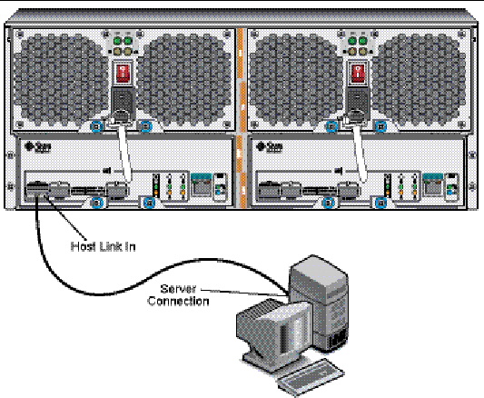
The management host directly manages the Sun Storage J4200/J4400 Array in-band over the mini-SAS host connection.
The mini-SAS cable for the host is not shipped automatically with the J4200/J4400 arrays; you must order or otherwise obtain an appropriate mini-SAS cable for your site.
To attach the J4200/J4400 SAS Host or SIM Link In connector to the data and management host:
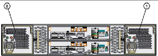
1. Locate the Host or SIM Link In (SIM 0) connector at the back of the tray (FIGURE 3-1 and FIGURE 3-2).
2. Connect the SAS Host or SIM Link In connector to a SAS port on the data host.
FIGURE 3-1 J4200 Array Connected to a Management System
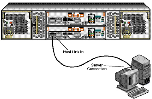
FIGURE 3-2 J4400 Array Connected to a Management System
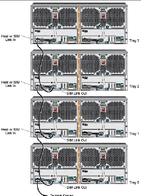
To interconnect a J4200/J4400 Array to a second or additional J4200/J4400s:
1. Locate the SIM Link Out port on the tray (Tray 0) attached to the data host. (FIGURE 3-1).
2. Locate the Host or SIM Link In port of the second tray (Tray 1).
3. Cable these two trays together with the provided mini-SAS cable.
FIGURE 3-3 shows a Sun Storage J4200 Array interconnected with three other J4200 arrays.
FIGURE 3-3 Interconnected J4200 Arrays
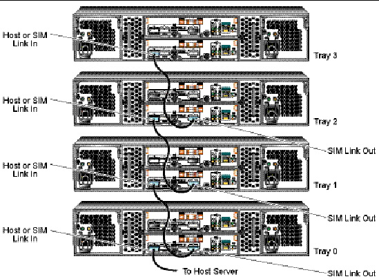
FIGURE 3-4 shows a Sun Storage J4400 array interconnected with three other J4400 arrays.
FIGURE 3-4 Interconnected J4400 Arrays
This section describes initial tray power-on and power-off procedures.
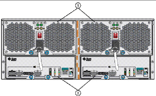
FIGURE 3-5 and FIGURE 3-6 show the J4200 and J4400 array rear components, including the two power supplies with universal power input connectors.
FIGURE 3-5 J4200 Array Rear Components
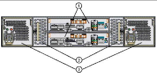
FIGURE 3-6 J4400 Array Rear Components
Use this procedure to turn power on for all J4200 trays installed in the cabinet (FIGURE 3-7). The J4200 does not have a power switch; power is turned on by connecting a plug into the array universal power input connectors.
FIGURE 3-7 Tray Power Connectors (J4200)
1. Plug the country-specific power cables into each of the tray universal power connectors.
2. Connect the power cables to the cabinet external power source.
3. Turn on the power switches (J4400 only).
4. Turn on the cabinet circuit breakers, if applicable.
While the tray powers on, the green and amber LEDs on the back of the tray turn on and off intermittently. Depending on your configuration, it can take several minutes for the tray to power on. When the power-on sequence is complete, the LEDs are steady green.
5. Check the status of each tray.
After the power-on sequence is complete, confirm the following:
If all tray and drive Ok/Power LEDs are steady green and the amber Service Required LEDs are off, the power-on sequence is complete and no faults have been detected.
Check to make sure the SAS connections are properly inserted.
Reseat the module to make sure that it is properly installed. If the LED is now green, the module is functioning properly. If the module remains blinking amber, contact Sun Customer Service Personnel.
Refer to the Sun Storage J4200/J4400 System Overview (820-3223-10) for additional troubleshooting information.
Remove power only when you plan to physically move the tray to another location. Most of the J4200/J4400 components are hot-swappable so you do not need to remove the power while replacing modules.

|
Caution - For products with multiple power cords, all power cords must be disconnected to completely remove power from the system. |
1. Stop all I/O from the host to the storage array.
2. Wait approximately two minutes until all disk drive status indicators have stopped flashing.
3. Turn off the power switches (J4400 only).
4. Disconnect the power cables from the power supplies.
You are now ready to use the disks in the J4200/J4400 array for storage. Refer to the Common Array Manager (CAM) documentation for your version of CAM for information about the management software. CAM documentation is available at the following URL:
http://docs.sun.com/app/docs/prod/stor.arrmgr
| Sun Storage J4200/J4400 Array Hardware Installation Guide | 820-3218-14 |
© © 2009 Sun Microsystems, Inc. All rights reserved.