
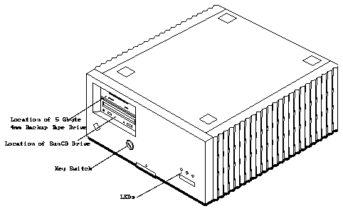
Figure 2-1
The SPARCserver 1000 System
Make sure you have read the Preface and Chapter 1 for safety precautions,
required tools, and an overview of the installation/replacement procedures
before beginning this chapter.
2.1.1
Powering Off the System
First halt the operating system and power off the SPARCserver 1000 system.
Caution -

To avoid damaging internal circuits, do not disconnect or plug in
any cable while power is applied to the system.
To shut down the system and give users a shutdown warning:
1. Back up the system files and data, if necessary.
2. Notify users that the system is going down.
3. Halt the system using the appropriate commands.
4. Wait for the system-halted message and the boot monitor prompt.
See the Solaris 2.x Handbook for SMCC Peripherals (P/N 801-4332-xx) or your
software system documentation for specific software commands.
Caution -

Do not disconnect the power cord from the wall socket when you
work on the server. This connection provides a ground path that prevents
damage from uncontrolled electrostatic discharge.
Warning -

Never move the system when the power is on. Failure to heed this
warning may result in catastrophic disk drive failure. Always power the
system off before moving it.
5. Turn the key switch on the front panel of the server to the Standby
position (fully counterclockwise).
See Figure 2-2.
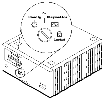
Figure 2-2
Key Switch in the Standby Position
6. Turn off the AC power switch on the system back panel.
Refer to Figure 2-3.
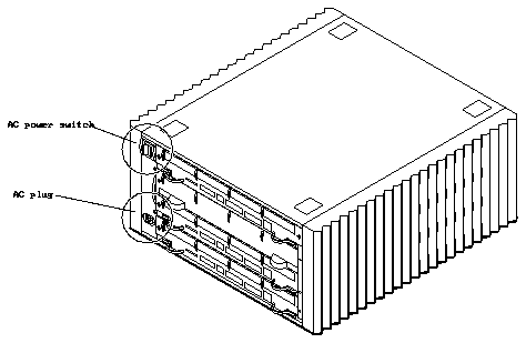
Figure 2-3
AC Power Switch and Plug
2.1.2
Removing the Front Panel and the EMI Shield
The 5 Gbyte 4mm backup tape drive unit fits into the upper half of the backup
device tray on the left side of the SPARCserver 1000 SCSI tray assembly. You
can access the SCSI tray assembly by first removing the front panel and the
electromagnetic interference (EMI) shield. The front panel rests in a groove cut
on the top front edge of the chassis (See Figure 2-4 on page 2-5).
To remove the front panel:
1. Remove the key from the key switch.
See Figure 2-2 on page 2-3.
2. Push up on the latch located on the bottom center of the front panel.
Place your fingers under the arrow embossed on the front panel and push
up to release the latch. Refer to Figure 2-4.
3. When the bottom of the panel is released, gently pull the bottom of the
front panel toward you and lift it off the chassis. Set the panel aside.
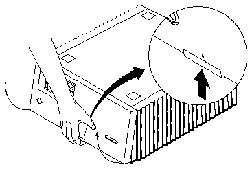
Figure 2-4
Removing the Front Panel
To remove the EMI shield:
1. Loosen the six captive retaining screws securing the EMI shield to the
chassis.
2. With your hands on the bottom of the EMI shield, pull the bottom toward
you to disengage it from the chassis. Set the EMI shield aside.
Refer to Figure 2-5.
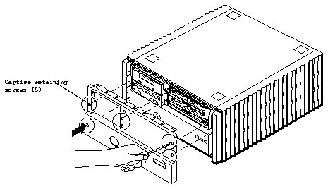
Figure 2-5
Removing the EMI Shield
2.1.3
Removing the SCSI Tray Assembly
The SCSI tray assembly mounts above the power supply in the front of the
SPARCserver 1000 system, behind the front cover and the EMI shield (See
Figure 2-6 on page 2-7). The backup device tray, on the left, contains a 5 1/4"
device bracket holding the SunCD drive and either the optional 5 Gbyte 4mm
backup tape drive or a half-height plastic filler panel. The SCSI disk drive tray,
on the right, contains two or four half-height disk drives. The control board is
mounted on top of the SCSI disk drive tray. The entire SCSI tray plugs directly
into an internal backplane; there are no cables in the interconnect. Removal of
the SCSI tray assembly involves releasing the retaining screws and pulling the
entire tray out of the server chassis (See Figure 2-6).
To remove the SCSI tray assembly:
1. Loosen the four captive screws securing the SCSI tray assembly to the
chassis.
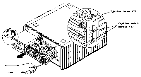
Figure 2-6
Removing the SCSI Tray Assembly
2. Lift the ejector levers on each side of the SCSI tray assembly
simultaneously until they point straight out; this action disengages the
SCSI tray assembly from the backplane.
3. Slide the SCSI tray out of the chassis. Be very careful--the tray is heavy!
Grasp the tray firmly as soon as it slides out far enough to do so.
Caution -

The SCSI tray is heavy and could fall if you do not have a firm grip.
2.1.4
Removing the 5 1/4" Device Bracket from the Backup Device Tray on
the SCSI Tray Assembly
The 5 1/4" device bracket holds the SunCD drive and either the optional
5 Gbyte 4mm backup tape drive or a plastic filler panel. The bracket, SunCD,
and tape drive or filler panel slip out of the backup device tray as a single unit.
(See Figure 2-7).
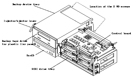
Figure 2-7
SCSI Tray Assembly
To remove the 5 1/4" device bracket from the SCSI tray assembly:
1. Disconnect the power and SCSI cables from the rear of the SunCD unit
(and from the 5 Gbyte 4mm backup tape drive, if present).
2. Remove the two M3 screws (at the rear of the backup device tray near the
bottom, on either side of the 5 1/4" device bracket) that secure the device
bracket to the SCSI tray assembly.
3. Slide the bracket with the SunCD and the tape drive or filler panel out of
the device tray from the front.
See Figure 2-8.
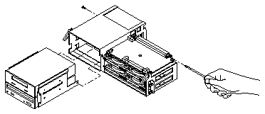
Figure 2-8
Removing the 5 1/4" Device Bracket from the Backup Device Tray
2.1.5
Removing the Tape Drive or the Plastic Filler Panel from the 5 1/4"
Device Bracket
1. To ease removal of the tape drive or filler panel from the device bracket,
place the bracket on the top of the SPARCserver 1000 unit so that the front
edge of the SunCD and tape drive hang slightly over the front edge of the
server.
2. Remove the four 6-32x1/4" screws (two on each side) that secure the tape
drive or filler panel to the bracket. Set the screws aside. You will use them
to secure the new tape drive to the device bracket.
3. Lift the tape drive or filler panel out of the 5 1/4" device bracket from the
top.
See Figure 2-6 on page 2-7.
If you are removing the original tape drive, set it on the ESD mat. Later, you
will need to enclose it in the new tape drive's packaging in order to return it.
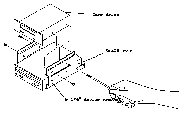
Figure 2-9
Removing the Tape Drive from the Device Bracket
2.2.1
Setting the SCSI Address
The SCSI tray accommodates up to six devices and the device controller, which
identifies each device by a unique numerical address (the SCSI ID) between 0
and 7. The SCSI ID number for the 5 Gbyte 4mm backup tape drive is 5 (101 in
binary).
Before inserting a new tape drive into the device bracket, set its SCSI address
to 5 (101 in binary) using the DIP switches on the right side of the back of the
drive.
1. With the tip of a ballpoint pen or other similarly shaped instrument, push
switch 1 (the farthest on the right) down.
Refer to Figure 2-10.
2. Lift switch 2 (to the left of switch 1) up.
3. Push switch 3 (to the left of switch 2) down.
4. Do NOT change any other switches on the tape drive.
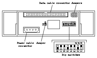
Figure 2-10
Device Addressing for the 5 Gbyte 4mm Backup Tape Drive
2.2.2
Inserting the Tape Drive into the SCSI Tray Assembly
Note -
Since the tape drive's serial number is located on the bottom of the
drive, you may wish to make a note of it before inserting the drive into the
device bracket.
1. To ease insertion of the tape drive into the device bracket, place the
bracket on the top of the SPARCserver 1000 unit so that the front edge of
the bracket hangs slightly over the front edge of the server.
2. With the front of the bracket hanging slightly over the front edge of the
server, slide the tape drive into the device bracket above the SunCD unit,
making sure that the front surfaces of the two drives are even with each
other.
See Figure 2-8 on page 2-9.
3. Install the four 6-32x1/4" screws to secure the tape drive to the bracket.
4. Slide the 5 1/4" device bracket (with tape drive installed) into the SCSI
tray assembly, from the front. Insert and tighten the two M3 retaining
screws.
Refer to Figure 2-7 on page 2-8.
5. Connect the SCSI cable at the rear of the tape drive and the SunCD,
making sure to match tabs and notches.
The connections can be made more easily if you attach the cable connector
nearest the terminator to the tape drive first.
6. Connect the power cable at the rear of the tape drive and the SunCD,
making sure to match the angled edges.
1. Slide the SCSI tray into the chassis.
See Figure 2-6 on page 2-7.
Caution -

Remember that the tray is heavy!
Caution -

If the ejector levers are not extended when you push the tray in, the
tray will not seat properly. Do not force the ejector levers down if the SCSI tray
resists seating in the backplane connectors. To force the tray in could damage
backplane or tray connector pins. Pull the tray out slightly, hold the ejector
levers outward, and try again. Gently close the ejector levers downward until
the tray is fully seated.
2. When the tray is halfway in, extend the ejector levers toward you.
Refer to Figure 2-6 on page 2-7.
3. While holding the ejector levers up, slide the SCSI tray into the chassis
until the ejector levers engage the metal on the chassis.
4. Seat the tray. Carefully push the levers down until they are vertical.
5. Using a flat-blade screwdriver, tighten the four captive retaining screws.
Note -
Due to normal machine tolerances, it is best to thread all four screws in
loosely (about 1-2 turns), then go around and tighten each screw.
2.3.2
Replacing the EMI Shield and the Front Panel.
To replace the EMI shield (Refer to Figure 2-5 on page 2-6):
1. Holding the sides of the EMI shield, align the top of the shield with the
chassis, and press inward.
2. Tighten the six captive retaining screws securing the EMI shield to the
chassis.
To replace the front panel (Refer to Figure 2-4 on page 2-5):
1. Rest the top of the front panel in the groove on the top front edge of the
chassis.
2. Push down on the panel until the latch located on the bottom center of the
front panel engages.
Note -
As the system starts up, watch for error messages from the POST
diagnostic program. If a terminal is not already part of the system, locate a TTY
terminal before continuing. See the SPARCserver 1000 System Service Manual.
1. Begin with a safety inspection of the system.
a. Put the key into the key switch on the front panel, making sure that it
is in the Standby position.
Refer to Figure 2-2 on page 2-3.
b. Check that the AC power switch on the system back panel is off.
Refer to Figure 2-3 on page 2-4.
c. Verify that the power cord is plugged into the server and into a wall
socket.
Caution -

Do not disconnect the power cord from the wall socket when you
work on the server. This connection provides a ground path that prevents
damage from uncontrolled electrostatic discharge.
2. Turn on the TTY terminal.
3. Turn on the AC power switch on the system back panel.
4. Turn the key switch to the On position.
See Figure 2-11 on page 2-15. You should see and hear several things
happen:
-
The left front panel LED (green) turns on immediately to indicate that the
DC power supply is receiving current.
-
The middle front panel LED (yellow) lights while POST runs for
approximately 60 seconds. After 60 seconds, this LED turns off if the tests
do not fail. If the LED remains lit after 60 seconds, a test has failed. Refer
to the SPARCserver 1000 System Service Manual.
-
The right front panel LED (green) lights to show that booting is successful
and the operating system is running. If this LED does not turn on and the
middle LED is on, a severe hardware fault exists. Refer to the SPARCserver
1000 System Service Manual.
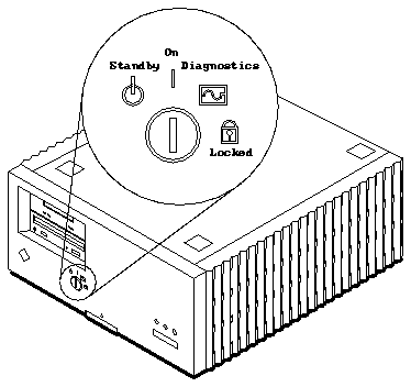
Figure 2-11
Key Switch in the On Position
5. Watch the terminal screen for possible error messages from the POST
diagnostic program.
POST tests subassemblies in the server and some interface paths between
subassemblies. At the conclusion of testing, POST automatically attempts to
reconfigure the system, omitting any parts of the system that have failed
diagnostics. If there are no faults, or if POST completes a successful
reconfiguration of the detected faults, the system boots.
If you wish to run diagnostics again, or if the system hangs, you need to press
the reset button behind the front panel. To access the reset button:
1. Remove the key from the key switch.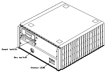
Figure 2-12 Location of the Reset Button
2. Remove the front panel.
See Figure 2-4 on page 2-5.
3. Insert the back of a pencil or other narrow object into the small opening
in the center of the metal face plate and press the reset button.
Refer to Figure 2-12.
4. After the system has been reset, replace the front plastic panel.
Rest the top of the front panel in the grooved channel on the top panel. Push
in on the lower portion of the front panel until it snaps back into place.
5. Return the key to the key switch.
Refer to the SPARCserver 1000 Storage Device User's Guide (P/N 801-2198-xx) or
the 5 Gbyte 4mm Backup Tape Drive Server User's Guide (P/N 801-4624-xx) for
directions on the use and care of the backup tape drive. See the Solaris 2.x
Handbook for SMCC Peripherals (P/N 801-4332-xx) or the documentation that
came with your operating system for the appropriate software commands to
run the 5 Gbyte 4mm backup tape drive on your system.
Warning -

Once the system is started, do not move or attempt to move the
SPARCserver 1000 with the system power on. Failure to heed this caution may
result in catastrophic disk drive failure. Always power the system off
completely before attempting a move.
