| C H A P T E R 2 |
|
Disk Drive, Air Management Sled, and Tabletop Cover FRUs |
This chapter provides instructions for removing and installing a disk drive, air management sled, and tabletop cover FRUs, and covers the following topics:
Checking and Performing the Correct Powerup Sequence
Assigning a Disk Drive as a Spare
If the Logical Drive Status is REBUILDING
Automatic Rebuild and Automatic Global Spare Assignments After a Failed Drive is Replaced
To replace a disk drive, you first remove the defective disk drive and then install a replacement drive. The drive module is hot-swappable. It is replaced while the RAID product is powered on.
Before replacing a disk drive, perform the following steps to ensure that you have identified the correct defective disk for removal.

|
Caution - To prevent any possibility of data loss, back up the data prior to removing disk drives. |
1. Examine the back of the RAID product and any attached expansion units, and record the cable connections.
2. Prepare the RAID product for the disk replacement:
a. From the Main Menu, choose "view and edit Configuration parameters," then choose "Drive-side Parameters."
b. Set the "Periodic Drive Check Time" option to 5 seconds, then confirm Yes when prompted.
3. Find the Channel number and SCSI target ID combination (i.e. Chl 0 ID 4) of the disk drive to be replaced:
a. From the Main Menu, choose "view and edit scsi Drives."
b. Locate the disk drive that has a status of BAD or FAILED in the Status column:
Write down the Channel number and SCSI target ID of the defective disk drive from the Chl and ID columns.
Write down the number of the associated logical drive, as shown in the LG_DRV column, that the defective disk drive is a member of.
4. Physically locate the defective disk drive using the Chl and ID numbers obtained in Step 3.
Refer to your Sun StorEdge Product Installation, Operation, and Service Manual for descriptions of ID locations.
5. If you are uncertain about the drive location of the defective drive, check your installation manual for drive ID locations or perform the following steps.
|
Note - The following steps only work if there is no I/O activity. |
a. On the Main Menu, choose "view and edit scsi Drives" and press Return.
b. Select the drive you want to identify and press Return.
c. Choose the "Identifying scsi drive" function.
d. Choose "flash all But selected drive" to flash the activity LEDs of all of the drives in the drive channel except the selected drive, and press Return.
e. Select a time interval and press Return.
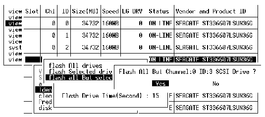
f. Confirm your choice by selecting Yes and pressing Return.
The read/write LED of all drives except the selected hard drive flash.

|
Caution - Failure to identify the correct disk drive may result in replacing the wrong disk drive and could cause a loss of data. Be sure that you have identified the correct disk drive. |

|
Caution - To prevent any possibility of data loss, back up the data prior to removing disk drives. |
Remove the defective disk drive with the following steps.
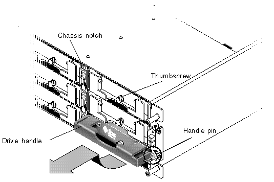
1. Unlock the locks with the provided key, and gently pull the plastic front bezel away from the front of the unit so that it drops down and is supported by the two hinged brackets on the sides.
2. Turn the thumbscrew of the defective disk drive counterclockwise several full turns until the thumbscrew and drive module are loosened.
3. Gently pull the release handle upward.
4. Pull the drive module out until the drive connector has fully disconnected from the midplane.
5. Wait 20 seconds for the drive to stop spinning and then remove it from the chassis.
To install the replacement disk drive, perform the following steps.
1. Gently slide the drive module into the drive slot until the handle pins slip into the chassis notch.
2. Lower the disk drive handle until it is vertical.
3. Press and hold the drive handle in while you press the thumbscrew in until it engages the threads.
4. Turn the thumbscrew clockwise until it is finger-tight.
5. Push the plastic front bezel onto the front of the unit until it is seated firmly, and use the key to lock the locks.
6. If the replaced drive is in a JBOD directly attached to a server, perform any operations your host software requires to recognize the new drive and bring it under software control.
7. Go to Scanning the New Drive and Related Procedures.
After you have replaced a disk drive, perform the following steps.
1. Check to see if the drive was automatically scanned onto the bus.
a. From the Main Menu, choose "view and edit scsi Drives."
b. Check the drive status of the disk drive.
The status field will specify NEW_DRV or USED_DRV until it is assigned as a GLOBAL or LOCAL spare with STAND-BY status.
2. If the disk drive was not automatically scanned, scan the replaced disk drive into the configuration with the following steps:
a. From the Main Menu, choose "view and edit scsi Drives." Select any disk drive in the list and press Return.
b. Choose "Scan scsi drive" and press Return. Select the Channel number, then the ID number of the replaced disk drive, and confirm Yes when prompted.
c. Verify that the message "Scanned SCSI drive successfully" is displayed.
3. From the Main Menu, choose "view and edit Logical drives" and use the following table to continue.
4. After replacing a failed drive, save the configuration settings to NVRAM as described in Saving the Configuration Settings to NVRAM. The NVRAM procedure applies to all drives.
When you save the NVRAM to file, you save the configuration of the array onto each of the hard drives. This step saves the current configuration onto the new hard drive.
Review the power-up sequence which you most recently used with the RAID product. If you are uncertain about the powerup sequence used, repeat the power-up sequence in the following order and see if it changes the logical drive status to GOOD.
1. Power up the RAID product and associated server as follows:
2. Check the logical drive status in the "view and edit Logical drive" window. If the status is GOOD, no further steps are needed.
3. If the logical drive status is FATAL FAIL, two or more disk drives may have failed, data may be lost, and you may have to create a new logical drive.
4. If the logical drive status is DRV ABSENT, replace the defective disk drive and assign the replacement drive as a global spare. See Assigning a Disk Drive as a Spare.
5. If the logical drive status is DRV ABSENT and the drive replacement is delayed, try to recover the defective drive so that it is operational during the wait period and you can make a full backup of the data.
a. On the firmware Main Menu, choose "view and edit Configuration parameters" and press Return.
b. Choose "Drive-side Parameters" and press Return.
c. Choose "Disk Access Delay Time" and press Return.
d. Change the value to 60 seconds and press Return.
e. Select Yes to confirm the setting.
g. Check the logical drive status in the "view and edit Logical drive" window.
If the status is GOOD, the drive has recovered and the logical drive is no longer in a critical state. The original defective disk drive should work correctly for a time but should still be replaced.
If the status is DRV ABSENT or DRV FAILED, replace the drive as soon as possible.
h. Back up the logical drive data onto another storage medium.
1. From the Main Menu, choose "view and edit scsi Drives."
2. Select the replaced disk drive and press Return (its LG_DRV membership should be NONE or an empty field).
3. Choose "Add global spare drive." Then select Yes to confirm when prompted.
4. Disable Periodic Drive Check Time:
From the Main Menu, choose "view and edit Configuration parameters," then choose "Drive-side Parameters."
Set the "Periodic Drive Check Time" option to Disabled, then confirm Yes. This procedure is now complete.
The rebuilding process refers to the rebuilding of the logical drive in which the data from a defective disk drive is restored to a global spare.
When you see the REBUILDING status, perform one of the two following procedures.
This procedure installs the new drive and assigns it as a global spare so that automatic rebuild of a logical drive will occur if a drive fails on any other logical drive.
|
Note - If a disk drive fails on another logical drive prior to the assignment of a new global spare, you will have to manually rebuild the logical drive. |
You can enable one or both of the following firmware features to expedite the rebuilding of a logical drive after a defective drive has been replaced:
|
Note - These features are Disabled by default. These features requires system resources and can impact performance. If you |
Periodic Auto-Detect Failure Drive Swap Check Time
This menu option periodically polls the unit to detect a replacement of a bad drive. If no spare drive is present within the array, the logical drive begins an automatic rebuild of a degraded RAID set if the firmware detects a bad drive replacement.
The drive-swap check time is the interval at which the controller checks to see whether a failed drive has been swapped. When a logical drive's member drive fails, the controller detects the failed drive (at the specified time interval). Once the failed drive has been swapped with a drive that has adequate capacity to rebuild the logical drive, the rebuild begins automatically.
The default setting is "Disabled," meaning that the controller does not auto-detect the swap of a failed drive. When "Periodic Drive Check Time" is set to "Disabled," the controller is not able to detect any drive removal that occurs after the controller has been powered on. The controller detects drive removal only when a host attempts to access the data on the drive.
1. Choose "view and edit Configuration parameters  Drive-side SCSI Parameters
  Periodic Auto-Detect Failure Drive Swap Check Time."
A list of intervals is displayed.
2. Choose the interval you want.
A confirmation message is displayed.
3. Choose Yes to confirm the setting.
By choosing a time value to enable the periodic drive check time, the controller polls all connected drives in the controller's drive channels at the assigned interval. Drive removal is detected even if a host does not attempt to access data on the drive.
Auto-Assign Global Spare Drive
This feature is Disabled by default. When you enable the "Auto-Assign Global Spare Drive" menu option, the system automatically assigns a global spare to the minimum drive ID in unused drives. This enables the Fibre Channel array to rebuild automatically without user intervention if a drive is replaced.
1. Choose "view and edit Configuration parameters  Drive-side SCSI Parameters
  Auto-Assign Global Spare Drive."
2. When the prompt Enable Auto-Assign Global Spare? appears, select Yes.
As soon as a faulty drive is replaced, the replacement drive is identified as a global spare drive.
An air management sled looks identical to the disk drive module; however, it is an empty box and is used to maintain optimum airflow in a chassis.
If you remove a disk drive and do not replace it, you can insert an air management sled to maintain the optimum airflow inside the chassis. You can install the air management sled by using the same procedure as Installing a New Disk Drive.
You can make a rack-ready array into a tabletop array or make a tabletop array into a rack-ready array. These procedures require attaching or removing a tabletop cover, also known as a tabletop skin. See FIGURE 2-3.
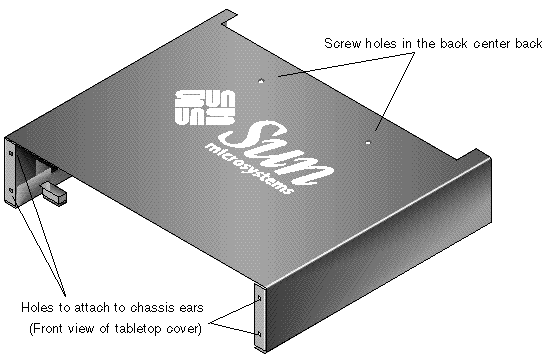
Perform the following steps to convert a rackmounted or rack-ready array to a tabletop array.
1. If attached, remove the bezel front cover by pulling it forward and downward. Then press the right bezel arm (hinge) towards the left side to release it from the chassis hole. The left hinge will release also. Note the location of the chassis bezel holes on each ear.
2. Remove the caps from the front left and right ears of the array by squeezing the left and right sides of each cap, and pressing the cap so that you turn the cap inward towards the center of the array until it is free.
3. Remove the array from the rack if it is rackmounted with the following steps. If it is not rackmounted, proceed with step 4.
a. Remove the screws which attach the front ears to the rack and which attach the array to the back brackets of the rack.
b. Slide the array out of the rack.
c. Remove the screws which attach the side rails to the array and store the rails and related screws.
4. On the top of the array, remove the top two back center screws with a Phillips No. 1 screwdriver and discard these screws.
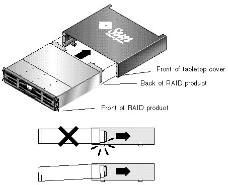
5. Slide the back of the array into the front of the tabletop cover until the front of the array is flush with the front of the tabletop cover. See FIGURE 2-4.
|
Note - As you slide the array into the cover, keep the back of the array tilted slightly upward to avoid bumping the edge of the array on the metal feet of the cover. |
6. Loosely attach the front of the tabletop cover to the front ears of the array with two 10-32 x 1/4-inch Phillips panhead screws on each side. See FIGURE 2-5.
7. Attach the top center back of the tabletop cover to the array with two new black flathead 4-40 x 1/4-inch screws and a Phillips No. 1 screwdriver.
8. Tighten the front screws (in step 6) with a Phillips No. 2 screwdriver.
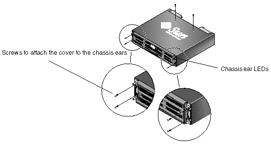
9. Put the caps back onto the ears:
a. Align the top and bottom edges of each cap with the top and bottom edges of each chassis ear.
b. While holding the side of the chassis with one hand, push the cap onto the ear with the other hand. Be sure to place the cap with LED labels on the right ear.
10. Insert the bezel arms into the chassis holes, and then lift and push the bezel onto the front of the chassis until it clicks and is secure.
Perform the following steps to convert a tabletop array to a rack-ready array.
1. If attached, remove the bezel front cover by pulling it forward and downward. Then press the right bezel arm (hinge) towards the left side to release it from the chassis hole. The left hinge will release also. Note the location of the chassis bezel holes on each ear.
2. Remove the caps from the front left and right ears of the array by squeezing and pressing each cap towards the center of the chassis until it is free.
3. Remove the 10-32 x 1/4-inch Phillips panhead screws which attach the tabletop cover to the array, with a Phillips No. 2 screwdriver, and discard these screws.
4. On the top of the array, remove the top two back center black flathead 4-40 x 1/4-inch screws with a Phillips No. 1 screwdriver and keep these screws.
5. Pull the front of the chassis until the chassis is completely removed from the tabletop cover.
6. Re-insert and secure the two black screws from Step 4 into the top center back of the rack-ready array with a Phillips No. 1 screwdriver.
7. Follow the rack kit installation instructions of the rackmount kit to install the array into a rack. After the RAID product is mounted in the rack, you can re-install the caps onto the ears and the bezel onto the front of the RAID product; these steps are also included in the rack kit instructions.
Copyright © 2004, Sun Microsystems, Inc. All rights reserved.