| C H A P T E R 8 |
|
Installing FRUs |
This chapter provides instructions for removing and installing field-replaceable units (FRUs) in Sun StorEdge 3120 SCSI arrays. These FRU components can be replaced by customers or by Sun service representatives.
This chapter covers the following topics:
|
Note - Be sure to follow Static Electricity and Other Precautions for all procedures. |
Most FRUs are hot-swappable, except for a few modules that are hot-serviceable. Hot-serviceable means that the module can be replaced while the array and hosts are powered up, but the connected hosts must be inactive.

|
Caution - Please follow the FRU procedures carefully to ensure successful FRU replacement. |
The following table lists the FRUs that are currently available. For additional FRUs, consult your sales representative or the Sun web sites.
Follow these steps to prevent damaging the FRUs:

|
Caution - To prevent any possibility of data loss, it is strongly recommended that you back up the data prior to removing disk drives. |
This section provides instructions for removing and installing disk drive, air management sled, and tabletop cover FRUs, and covers the following topics:
To replace a disk drive, you first remove the defective disk drive and then install a replacement drive. The drive module is hot-swappable; it is replaced while the array is powered on.

To receive automatic email notification of a disk drive failure, set up Sun StorEdge Configuration Service or Sun StorEdge Diagnostic Reporter. For details, refer to the Sun StorEdge 3000 Family Diagnostic Reporter User's Guide or the Sun StorEdge 3000 Family Configuration Service User's Guide.
Before replacing a disk drive, perform the following steps to ensure that you have identified the correct defective disk for removal.

|
Caution - To prevent any possibility of data loss, it is strongly recommended that you back up the data prior to removing disk drives. |
1. Examine the back of the array, and record the cable connections.
2. Physically locate the defective disk drive.
An amber LED next to a drive on the front panel of the JBOD indicates a failed disk drive. For details, see Front-Panel LEDs.
3. Record the Chl and ID number for the defective disk drive (for example, Chl 0 ID 4).
For descriptions of ID settings, see Fixed Drive IDs.
4. (Optional.) In Sun StorEdge Configuration Service, a red icon  in the main window indicates a JBOD drive failure. Review the error log to confirm the disk drive ID for the failed drive.
For details on the Sun StorEdge Configuration Service main window, see Main Window.
5. (Optional.) In Sun StorEdge CLI, run the show enclosure-status command. If the drive status is "Absent" the drive may have failed, or has been removed from the chassis.
For details on the show enclosure-status command, see show enclosure-status.

|
Caution - Failure to identify the correct disk drive may result in replacing the wrong disk drive and could cause a loss of data. Be sure that you have identified the correct disk drive. An amber drive LED indicates a drive failure. For details, see Front-Panel LEDs. |

|
Caution - To prevent any possibility of data loss, it is strongly recommended that you back up the data prior to removing disk drives. |
Remove the defective disk drive with the following steps.
1. Unlock the locks with the provided key, and gently pull the plastic front bezel away from the front of the unit so that it drops down and is supported by the two hinged brackets on the sides.
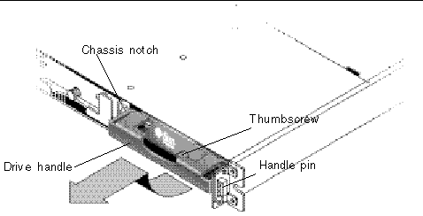
2. Turn the thumbscrew counterclockwise several full turns until the thumbscrew and drive module are loosened.
3. Gently pull the release handle upward.
4. Pull the drive module out until the drive connector has fully disconnected from the midplane.
5. Wait 20 seconds for the drive to stop spinning and then remove it from the chassis.
To install the replacement disk drive, perform the following steps.
1. Gently slide the drive module into the drive slot until the handle pins slip into the chassis notch.
2. Lower the disk drive handle until it is vertical.
3. Press and hold the drive handle in while you press the thumbscrew in until it engages the threads.
4. Turn the thumbscrew clockwise until it is finger-tight.
5. Push the plastic front bezel onto the front of the unit until it is seated firmly, and use the key to lock the locks.
A green drive LED indicates a functional drive. For details, see Front-Panel LEDs.
6. If the replaced drive is in a JBOD directly attached to a server, perform any operations your host software requires to discover the new drive and bring it under software control.
For specific operating system instructions, see .
7. (Optional.) If you are using Sun StorEdge Configuration Service, you can discover the new drives using the software.
For instructions, refer to the Sun StorEdge 3000 Family Configuration Service User's Guide.
The rebuilding process refers to the rebuilding of the logical drive in which the data from the defective disk drive is moved onto the global spare.
When you see the REBUILDING status, perform one of the two following procedures.
This procedure installs the new drive and assigns it as a global spare so that automatic rebuild of a logical drive will occur if a drive fails on any other logical drive on the array.
|
Note - If a disk drive fails on another logical drive prior to the assignment of a new global spare, you will have to manually rebuild the logical drive. |
An air management sled looks identical to the disk drive module; however, it is an empty box and is used to maintain optimum airflow in a chassis.
If you have removed a disk drive and do not replace it, you can insert an air management sled to maintain the optimum airflow inside the chassis. You can install the air management sled by using the same procedure as Installing a New Disk Drive.
Topics covered in this section are:
The following power specifications apply to the power supply and fan modules:

|
Caution - To avoid damage to equipment, do not remove a power supply/fan module without a working replacement. |
1. Be sure to follow Static Electricity and Other Precautions.
2. Turn off the power, and then remove the AC cord locks (if applicable) and the power cable.
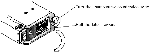
3. Turn the thumbscrew at the top of the power supply latch counterclockwise until the thumbscrew is disengaged from the power supply.

4. Pull the latch forward about 90 degrees to disconnect the power supply/fan module from the midplane.
5. Pull the power supply/fan module out of the chassis.
1. Slide the new module into the fan and power supply slot.
2. Push the latch back so that the power supply is fully inserted into the chassis.
3. Turn the thumbscrew at the top of the power supply latch clockwise until it is finger-tight, to secure the module.
|
Note - To ensure that a thumbscrew is finger-tight, tighten it with a screwdriver and then loosen the thumbscrew counterclockwise a quarter-turn. |
4. Attach the power cable and reinstall the AC cord locks if applicable.

|
Caution - To avoid damage to equipment, do not remove a power supply/fan module without a working replacement. |
1. Be sure to follow Static Electricity and Other Precautions.
2. Turn off the power and remove the power cable.
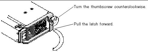
3. Turn the thumbscrew at the top of the power supply latch counterclockwise until the thumbscrew is disengaged from the power supply.

4. Pull the latch forward about 90 degrees to disconnect the power supply/fan module from the midplane.
5. Pull the power supply/fan module out of the chassis.
1. Slide the new module into the fan and power supply slot.
2. Push the latch back so that the power supply is fully inserted into the chassis.
3. Turn the thumbscrew at the top of the power supply latch clockwise until it is finger-tight, to secure the module.
|
Note - To ensure that a thumbscrew is finger-tight, tighten it with a screwdriver and then loosen the thumbscrew counterclockwise a quarter-turn. |
4. Connect the DC power cable to the DC source.
Check the DC cable part number and wire labels carefully before connecting the cable to the source (see the table below). GND = Chassis Ground.
5. To extend the length of the DC power cable as needed: Strip the last 1/4-inch of the cable, insert it into a provided Panduit tube, and crimp the tube.
6. Attach the power cable to the array.
The Sun StorEdge 3120 SCSI array box FRU includes a chassis, its drive midplane, and its backplane. This product is ordered to replace a box that has been damaged or whose midplane, backplane, or terminator module has been damaged.
To make a fully functional array, you need to add the following parts from the replaced array:
To install the individual modules, use the replacement instructions provided in this guide.
To configure the array, see Connecting Your SCSI Array.
To replace the chassis frame of an existing JBOD, perform the following steps.

|
Caution - Connected hosts must be inactive during this replacement procedure. |
|
Note - Be sure to follow Static Electricity and Other Precautions for all procedures. |
1. Power off both power supply modules on the defective array.
2. Ensure all SCSI cables attached to the I/O module are labeled clearly.
3. Write down the defective array's cabling configuration.
4. Write down the SCSI ID switch setting, right or left.
The IDs assigned for disks 1 through 4 depend on the switch settings on the array. The right switch setting uses IDs 8, 9, 10, and 11. The left switch setting uses IDs 12, 13, 14, and 15.
5. Remove all SCSI cables attached to the I/O module.
6. Label each disk drive with its disk slot position in the array.
7. Remove the power supply modules and disk drives from the defective array.
8. Remove the defective chassis.
9. Obtain the replacement chassis.
10. Re-install all previously removed modules in their original positions into the replacement array.
11. Re-install all SCSI and power cables in their original positions.
12. Set the SCSI ID switch to right or left depending on your previous configuration.
|
Note - SCSI IDs are set based on the switch setting on the array when it is powered on. If you change the switch setting, the SCSI IDs will change after you power off, and then power on. |
13. Power on both power supply modules on the replacement array.
14. See Connecting Your SCSI Array for instructions about configuring the JBOD.
Copyright © 2004, Sun Microsystems, Inc. All rights reserved.