| Skip Navigation Links | |
| Exit Print View | |

|
Sun Blade X6275 M2 Server Module Service Manual |
About This Documentation (PDF and HTML)
Server Module and Components Overview
About the Sun Blade 6000 Modular System Chassis
Powering On and Off the Server Module
Preparation Procedures for Service and Operation
Preparing the Server for Service
Preparing the Server for Operation
Component Removal and Installation Procedures
Removing and Installing Flash Modules
Removing and Installing the Energy Storage Modules
Removing and Installing the Service Processor Board
Removing and Installing USB Flash Drives
Removing and Installing a CPU and Heatsink Assembly
How to Replace the Motherboard Assembly
Diagnostic and Maintenance Information and Procedures
Diagnosing Server Module Hardware Faults
Using the DIMM and CPU On-Board Test Circuitry
Multi-Port Cable Connection Overview
How to Attach a Multi-Port Cable
Clearing CMOS NVRAM and Resetting Passwords
How to Clear the NVRAM Using the BIOS Setup Utility
How to Clear the CMOS and Reset the BIOS Password Using Jumpers
Recovering from Corrupted Service Processor Firmware
How to Recover the SP Firmware Using the Preboot Menu
BIOS Power-On Self-Test (POST) Codes
Server Module Maintenance Procedures and Information
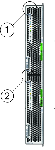
Two pairs of LEDs inside the front panel of your server (one pair for each node) display a set of two-digit hexadecimal POST codes. You can use these LEDs to discern the status of the server and diagnose server- and node-related issues. To view the LEDs, you need to look through the front panel and into the server module at the locations shown in the following illustration.
The illustration and table below show the location and describe the function of the Post Code LEDs.

|
Table 1 POST Codes For the Front Panel POST Code LEDs
|
See Also: