| Skip Navigation Links | |
| Exit Print View | |

|
Sun Blade X3-2B (formerly Sun Blade X6270 M3) Installation Guide |
| Skip Navigation Links | |
| Exit Print View | |

|
Sun Blade X3-2B (formerly Sun Blade X6270 M3) Installation Guide |
Sun Blade X3-2B Model Name Change
Getting the Latest Firmware and Software
About the Installation Procedure
About Server Features and Components
Preparing to Install the Server Module
Attach the 3-Cable Dongle to the Server Module
Attach a VGA Monitor to the Dongle Video Connector
Attach a Keyboard and Mouse to the Dongle or Server Module
Attach a Serial Device to the Dongle
Determining the Oracle ILOM SP IP Address
Logging In to Server Module SP Oracle ILOM
Accessing the Server Module Console Through Oracle ILOM
Setting Up Software and Firmware
Accessing Oracle System Assistant
Set Up Software and Firmware (Oracle System Assistant)
Setting Up an Operating System and Drivers
Preparing the Storage Drives to Install an Operating System
Prepare the Storage Drives (Oracle System Assistant)
Make a Virtual Drive Bootable (LSI WebBIOS Utility)
Configuring the Preinstalled Oracle Solaris OS
Oracle Solaris OS Documentation
Configure Preinstalled Oracle Solaris 11
Configuring Preinstalled Oracle VM Software
Oracle VM Server Configuration Worksheet
Configure the Preinstalled Oracle VM Server
Getting Started With Oracle VM
Configuring the Preinstalled Oracle Linux OS
Oracle Linux Configuration Worksheet
Configure the Preinstalled Oracle Linux OS
Register and Update Your Oracle Linux OS
Troubleshoot Installation Issues
Powering Off the Server for Graceful Shutdown
Powering Off the Server for Immediate Shutdown
Troubleshooting Server Power States
Technical Support Information Worksheet
Locating the System Serial Number
Getting Server Firmware and Software
Firmware and Software Access Options
Available Software Release Packages
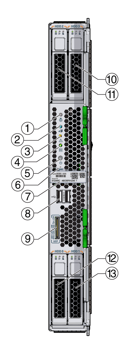
The following illustration calls out the front panel features.
Figure 1 Server Module Front Panel Features

|
The topics below describe the function of the front panel components.
This section describes the functions of the front panel LEDs and buttons (see Figure 1 ).
![]() Locate LED and Button:
Locate LED and Button:
White light: Press the button to light the LED and identify server within Oracle ILOM. Also used in some Oracle ILOM procedures.
![]() Ready to Remove LED:
Ready to Remove LED:
Blue light. Main power off. Safe to remove.
![]() Service Action Required LED:
Service Action Required LED:
Amber light. Signals that a fault condition has occurred and an investigation of the issue is required.
![]() OK/Power LED:
OK/Power LED:
Green light. Modes:
 Power button:
Press briefly to toggle the server between standby and full power.
 NMI button:
For Oracle Service use only. Do not press.
This section describes the front panel components (see Figure 1 ).
Serial number label: Unique number identifies server model within Oracle systems.
USB 2.0 ports (two): Removable storage.
Universal connector port (UCP): Used for multiport (dongle) cable.
Hard drives (HDDs) or solid state disks (SSDs): Server module storage drives.