3 Servicing CRUs That Do Not Require System Power Off
This chapter describes how to remove and replace the hot-swappable components in Oracle Database Appliance. Hot-swappable means that these components can be replaced with the system powered on.
Note:
Hot-swappable components can also be replaced with the system powered off. If you choose this method, first power off the system as described in Chapter 2, Preparing Oracle Database Appliance for Service.The following topics are covered:
Oracle Database Appliance X3-2/X4-2/X5-2 Server Node Hot-Swappable Components
-
Oracle Database Appliance X3-2/X4-2/X5-2 Storage Shelf Hot-Swappable Components
-
Oracle Database Appliance (Original Version) Hot-Swappable Components
Oracle Database Appliance X3-2/X4-2/X5-2 Server Node Hot-Swappable Components
This section describes replacing hot-swappable components for the Oracle Database Appliance X3-2, Oracle Database Appliance X4-2, and Oracle Database Appliance X5-2 for service. If you have Oracle Database Appliance (original version), go to Oracle Database Appliance (Original Version) Hot-Swappable Components.
Hot-swappable components are those that can be removed and installed while the system and the server nodes are running without requiring any administrative tasks. These are designated as Customer Replaceable Units (CRUs).
Refer to the following table for hot-swap component instructions for your appliance.
Note:
The links in the following table take you to instructions outside of the Oracle Database Appliance library to the Sun Server X3-2, Sun Server X4-2, and Oracle Server X5-2 documentation libraries. Use your browser's Back button to return to the Oracle Database Appliance library.| ODA X3-2 | ODA X4-2 | ODA X5-2 |
|---|---|---|
Oracle Database Appliance X3-2/X4-2/X5-2 Storage Shelf Hot-Swappable Components
This section describes replacing hot-swappable components for the Oracle Database Appliance X3-2, Oracle Database Appliance X4-2, and Oracle Database Appliance X5-2 for service. If you have Oracle Database Appliance (original version), go to Oracle Database Appliance (Original Version) Hot-Swappable Components.
Hot-swappable components are those that can be removed and installed while the system and the server nodes are running without requiring any administrative tasks. These are designated as Customer Replaceable Units (CRUs).
Caution:
Data loss. Do not remove power from both power supplies of the storage shelf or storage expansion shelf (if equipped) while the database is running. If you must power off the storage shelf or expansion storage shelf, stop the database first.Note:
After a physical insertion or removal action of a storage shelf component (such as a disk or SAS cable), you should wait before performing the next action to allow the system software to fully process the event. This could take up to 3 minutes to complete.Replacement Procedures (CRU)
Oracle Database Appliance X3-2/X4-2 (DE2-24P) and Oracle Database Appliance X5-2 (DE2-24C) storage shelf components can all be replaced while the storage shelf is powered-on and running. They include:
Replace a Storage Shelf HDD or SSD
- Locate the failed drive on the front of the chassis.
Caution:
Equipment damage. Do not remove a drive unless you have an immediate replacement. - Press the latch to release the drive lever.
- Pull the drive lever to the open position.
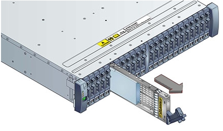
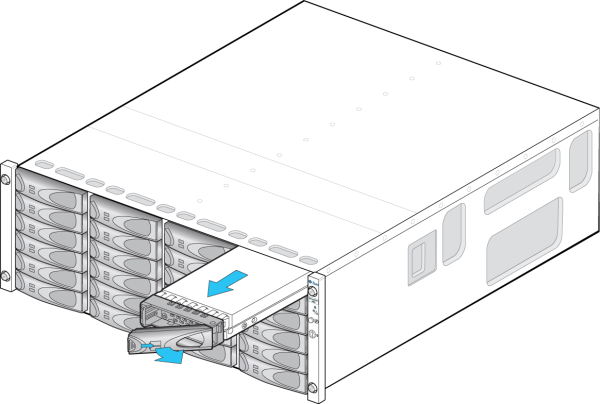
- Grasp the middle of the drive body and pull it toward you to remove it from the chassis.
Example showing the DE2-24P:
Example showing the DE2-24C:
- Open the drive lever on the replacement drive.
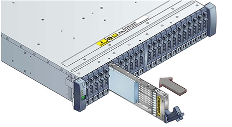
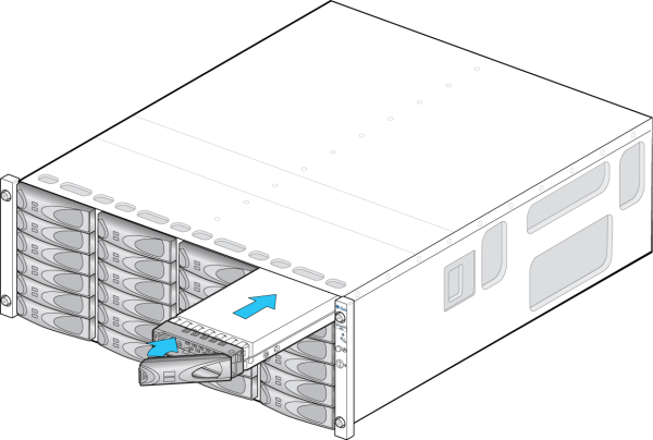
- While constantly pushing toward the pivot point of the lever, slide the drive fully into the
chassis slot.
Example showing the DE2-24P:
Example showing the DE2-24C:
Replace a Storage Shelf Power Supply
The storage shelf and the storage expansion shelf each have two power supplies. Indicators (LEDs) on the power supplies indicate their operation state.
The power supplies are redundant and one can be replaced while the appliance is running.
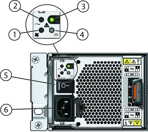
| Callout | Description |
|---|---|
|
1
|
Fan fail indicator
|
|
2
|
AC power fail indicator
|
|
3
|
Power supply status indicator
|
|
4
|
DC power fail indicator
|
|
5
|
On/Off switch
|
|
6
|
AC connector
|
If any of the LEDs [1 - 4] are amber, or if the power supply status indicator does not light, replace the power supply.
- Ensure the power supply on/off switch is in the "O" off position.
- Disconnect the power cord tie strap from the power cord, and unplug the power cord from the power supply.
- Release the lever/ejection arms.
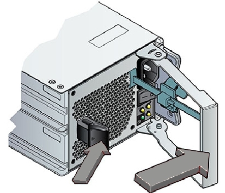
- Pull the power supply module out of the chassis.
- Open the lever/ejection arms on the replacement power supply.
- Slide the replacement power supply module into the chassis.
Be careful to not bend the pins.
- Close the lever/ejection arms.
Push the lever fully closed until you hear or feel a click.
Replace a Storage Shelf I/O Module
Storage Shelf SAS I/O modules are fully redundant and can be replaced while the appliance is running.
- Disconnect the cables from the I/O module.
Be sure to mark the cables so you can return them to their proper connectors.
Example showing the DE2-24P:

Example showing the DE2-24C:
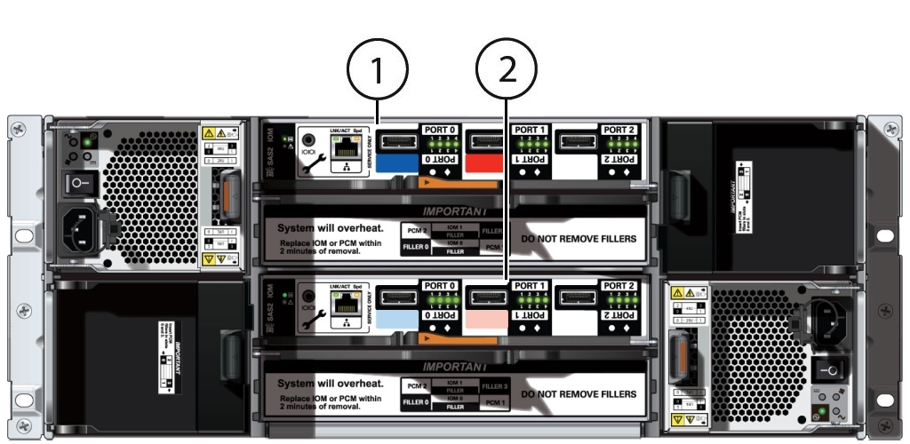
Callout Description 1I/O module 1 (top)2I/O module 0 (bottom) - Using your thumb and forefinger, squeeze the release button [1] toward the lever hole to
release the lever [2].
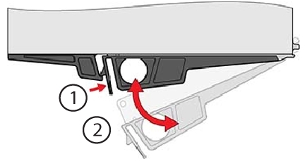
- Grasp the lever and remove the I/O module.
Caution:
Equipment damage. Be careful not to damage the connector pins at the back of the I/O module. - Open the lever in the new I/O module if it is not already open.
- Slide the new I/O module into the disk shelf.
- Reconnect the cables.
- Verify that the new I/O module is working correctly.
-
After approximately 60 seconds, the power LED should be solid green and the Fault/Locate LED should be off.
-
For each port that has a cable connected, all four activity LEDs should be solid green.
-
Oracle Database Appliance (Original Version) Hot-Swappable Components
This section describes replacing hot-swappable components for the Oracle Database Appliance (original version) for service. If you have Oracle Database Appliance X3-2, Oracle Database Appliance X4-2, or Oracle Database Appliance X5-2, go to Oracle Database Appliance X3-2/X4-2/X5-2 Server Node Hot-Swappable Components or Oracle Database Appliance X3-2/X4-2/X5-2 Storage Shelf Hot-Swappable Components.
Hot-swappable components are those that can be removed and installed while the system and the server nodes are running without requiring any administrative tasks.
Note:
After a physical insertion or removal action of a storage shelf component (such as a disk or SAS cable), you should wait before performing the next action to allow the system software to fully process the event. This could take up to 3 minutes to complete.In Oracle Database Appliance (original version), the following devices are hot-swappable:
Storage and Boot Drives. See Servicing Storage Drives and Boot Drives (CRU).
Fan modules. See Servicing Fan Modules (CRU).
Power supplies. See Servicing Power Supplies (CRU).
Servicing Storage Drives and Boot Drives (CRU)
Oracle Database Appliance (original version) has 24 storage drives, located in the front of the chassis, and each server node has 2 boot drives, located in the rear. All storage drives and boot drives are hot-swappable.
See Storage and Boot Drive Status Indicators for specific information about drive status LEDs.
This section includes:
Storage and Boot Drive Locations
Appliance storage drives. Appliance storage drives are installed at the front of Oracle Database Appliance (original version). Drive numbering is listed on the drive label on the right side of the appliance [1].
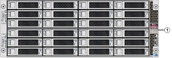
The following table shows slot numbering and the type of the storage drive supported in each slot.
Note:
The appliance might include both mechanical hard disk (HDD) and solid state (SSD) drives. Both use the same 2.5 inch disk drive bracket. An SSD has a smaller footprint inside of the bracket than an HDD.| Drive Slot Numbers and Types Supported | Drive Slot Numbers and Types Supported | Drive Slot Numbers and Types Supported | Drive Slot Numbers and Types Supported |
|---|---|---|---|
|
SSD20 |
SSD21 |
SSD22 |
SSD23 |
|
HDD16
|
HDD17
|
HDD18
|
HDD19
|
|
HDD12
|
HDD13
|
HDD14
|
HDD15
|
|
HDD8
|
HDD9
|
HDD10
|
HDD11
|
|
HDD4
|
HDD5
|
HDD6
|
HDD7
|
|
HDD0
|
HDD1
|
HDD2
|
HDD3
|
Server Node boot drives. Each appliance server node contains two boot drives that are installed in the back of Oracle Database Appliance and identified on the rear drive panel label.
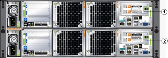
The following table shows the location and numbering of the boot drives.
| Callout | Drive Locations and Identification |
|---|---|
|
1
|
Boot Drives at the back of server node 1. Location and identification of the server node 1
boot drives as listed in Oracle ILOM:
|
|
2
|
Boot Drives at the back of server node 0. Location and identification of the server node 0
boot drives as listed in Oracle ILOM:
|
Remove a Storage Drive
- Identify the storage drive that you want to remove.
If a drive has failed, its amber Service Required LED will be lit. For information on drive status LEDs, see Storage and Boot Drive Status Indicators. For specific drive locations, see Storage and Boot Drive Locations.
- Remove a storage drive.
- On the drive you plan to remove, push the storage drive release button to open the latch [1].
- Grasp the latch and open it to a 45 degree angle [2].
- Using the latch, slowly pull the drive straight out of the drive
slot, not sideways or vertically.
Do not use much force on the latch when removing the drive.
Caution:
Equipment damage. Do not use the latch as an ejector. Do not bend it too far to the right.Caution:
Equipment damage. Always replace a drive with another drive to maintain proper airflow.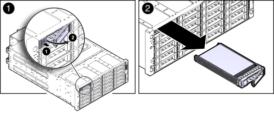
Install Storage Drive
- Determine the drive slot location for the replacement drive.
Drives are physically addressed according to the slot in which they are installed. See Storage and Boot Drive Locations for drive locations.
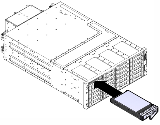
- Slide the drive into the drive slot until it is fully seated.
- Close the latch to lock the drive in place.
- Run the fwupdate command and verify that it lists all the disks under the DISKS section.
Remove a Boot Drive
- Identify the boot drive that you want to remove.
The amber Service Required LED might be lit. For specific drive locations, see Storage and Boot Drive Locations.
- Remove the boot drive.
- To open the drive door, slide the latch to the left.
- Pull the door open [2].
- On the drive you plan to remove, push the storage drive release button to open the latch [2].
- Grasp the latch and open it to a 45 degree angle [2].
- Using the latch, slowly pull the drive straight out of the drive
slot, not sideways or vertically [2].
Do not use much force on the latch when removing the drive.
Caution:
Equipment damage. Do not use the latch as an ejector. Do not bend it too far to the right.Caution:
Equipment damage. Close the door after removing a boot drive to prevent overheating due to improper airflow.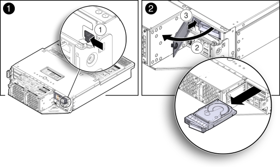
Install a Boot Drive
- Determine the drive slot location for the replacement drive.
Drives are physically addressed according to the slot in which they are installed. See Storage and Boot Drive Locations for drive locations.
- Pull open the rear drive door.
- Slide the drive into the drive slot until it is fully seated [1].
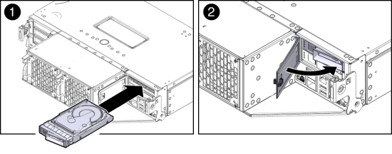
- Close the drive latch to lock the drive in place.
- Close the drive door and ensure that the door latch engages [2].
Caution:
Equipment damage. Close the door after removing a boot drive to prevent overheating due to improper airflow. - Run the following command to ensure that the OS sees the replacement
disk.
# lsscsi -v | grep ATA
[0:0:0:0]    disk    ATA      SEAGATE ST95001N n/a   /dev/sda
[1:0:0:0]    disk    ATA      SEAGATE ST95001N n/a   /dev/sdb
Servicing Fan Modules (CRU)
Each Oracle Database Appliance (original version) server node contains two fan modules. Each fan module contains a single, dual-motor, 80 mm, counter-rotating fan assembly that contains two fans. Each fan module is hot-swappable. For specific information about fan status LEDs, see Server Node Fan Indicators.
When a server node is removed from the system, the fans provide sufficient cooling for all 24 front disks and the server node. A door automatically closes off the vacant server node slot to ensure proper cooling. When the server node is replaced, its two fans also cool the 24 front disks and provide cooling to the second server node.
Caution:
Equipment damage. If a fan module fails, replace it as soon as possible.The following topics are covered in this section:
Detecting a Fan Module Failure
The following LEDs are lit when a fan module fault is detected:
Front and rear Service Required LEDs located on each server node
REAR HDD/PS/FAN LED located on the front of each server node
Fan Fault Status LED located on the faulty fan module
The system over-temperature LED for a server node might light if a fan fault causes an increase in server node operating temperature. See Server Node Status Indicators for more information about server node LEDs.
Remove a Fan Module
- Identify the faulty fan module with its amber LED.
When a fan fails, the Service Required LED lights amber. For information about fan status LEDs, see Server Node Fan Indicators.
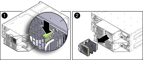
- To remove the faulty fan module, press down on the fan release lever [1].
- While holding the release lever down, use the handle on the fan
module to pull it out of the server node [2].
The fan door swings shut to ensure proper cooling.
Install a Fan Module
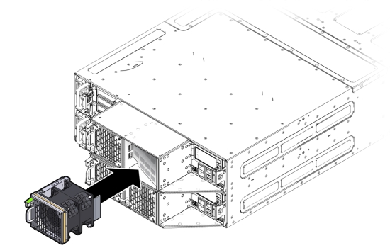
- Align the fan module in the fan door and slide it into the server
node.
The extender on the side of the fan module pushes the fan door open, allowing the fan module to enter.
- Apply firm pressure to fully seat the fan module.
The fan release lever engages when the fan is fully seated.
- Verify that the Fan Fault Status LED on the replacement fan module is lit green.
- Verify that the following fault LEDs on the applicable server
node are off.
- Front and rear Service Required LEDs located on the applicable server node
- REAR HDD/PS/FAN LED located on the front of the applicable server node
See Server Node Status Indicators for more information about system LEDs.
Servicing Power Supplies (CRU)
Oracle Database Appliance (original version) is equipped with two hot swappable power supplies. They are redundant, meaning that the system can operate with a single power supply. This allows you to remove and replace a power supply without shutting the system down.
If a power supply fails and you do not have a replacement available, to ensure proper airflow, leave the failed power supply installed in the system.
For information about power supply status LEDs, see Power Supply Status Indicators.
This section includes:
Detecting a Power Supply Failure
The following LEDs light up when the system detects a power supply fault:
Front and rear Service Required LEDs located on each server node
REAR HDD/PS/FAN LED located on the front of each server node
Service Required LED located on the faulty power supply
See Server Node Status Indicators on page 1-6 for information about these LEDs.
Remove a Power Supply
Caution:
Hazardous voltages. To reduce the risk of electric shock and danger to personal health, follow the instructions.- Identify which power supply (0 or 1) requires replacement.
A lit Service Required LED on a power supply indicates that a failure was detected. For information about power supply status LEDs, see Power Supply Status Indicators.
- Disconnect the power cord from the faulty power supply.
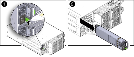
- Grasp the power supply handle and press the release latch [1]).
- Pull the power supply out of the chassis [2].
Install a Power Supply
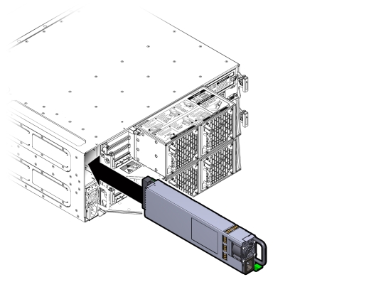
- Align the replacement power supply with the empty power supply chassis bay.
- Slide the power supply into the bay until it is fully seated.
The release latch engages when the power supply is fully seated.
- Reconnect the power cord to the power supply and verify the following:
-
The power supply AC Present LED is lit
-
The power supply Service Required LED is off.
-
- Verify that the following LEDs are off:
-
Service Required LEDs located on the front of both server nodes
-
REAR HDD/PS/FAN LED located on the front of both server nodes
See Storage and Boot Drive Locations for more information about system LEDs.
-