34 Dynamic Resource Provisioning with Oracle VM Server for SPARC
Oracle Enterprise Manager Cloud Control integrates with Enterprise Manager Ops Center to create and manage virtual datacenters (vDC). Within the vDC, a vServer appears to users as a complete system, which they can optimize on demand as a DBaaS or MWaaS private cloud.
34.1 Integration for a PaaS Solution
In Oracle Enterprise Manager Ops Center, the IaaS cloud platform service is a virtual datacenter (vDC), a virtual environment supported by pooled servers, storage, and network resources. A cloud administrator sets up the vDC to run Oracle VM Servers for SPARC (logical domains). Enterprise Manager Cloud Control users are creating vServers in the logical domains automatically, as needed. Each vServer draws its requirements from the resources of the vDC.
This section explains how to create the vDC in Enterprise Manager Ops Center and how to connect it to Enterprise Manager Cloud Control.
34.1.1 Prerequisites
-
Enterprise Manager 12c Cloud Control Release 5 with Virtual Service Adaptor configured to connect to Ops Center's Enterprise Controller. See Getting Started with Dynamic Resource Provisioning.
-
Enterprise Manager Ops Center Release 3 with managed storage and network assets. See Oracle Enterprise Manager Ops Center
Installation for Oracle Solaris Operating SystemandConfigure Referencefor information about installing the product and discovering assets. -
Oracle Enterprise Manager Ops Center Client Kit, which includes modifications to enable communication between the two software products. This kit is available from My Oracle Support to https://support.oracle.com/epmos/faces/PatchDetail?patchId=21190506.
The minimum requirement for Ops Center is the co-located configuration: one system hosts the Enterprise Controller, one Proxy Controller, and an embedded Oracle database.
-
Requirements for Enterprise Controller:
-
A minimum of T4-1 Sun Server
-
Same or higher version of Oracle Solaris 11 as the version to be provisioned on vServers running Oracle VM Server for SPARC. Supported versions are Oracle Solaris 11, 11.1, and 11.2 but, for optimal performance use the latest SRU of Oracle Solaris 11.2.
-
-
Requirements for Proxy Controller:
-
Co-located with Enterprise Controller or running in a system with the same minimum requirements for server, network, and operating system as for the Enterprise Controller.
-
-
Requirements for Oracle VM Server for SPARC control domain:
-
Oracle VM Server for SPARC 3.1 or later
-
Oracle Solaris 11, 11.1, and 11.2. The version must be the same or later than the version to run in the vServer. To provide different versions of Oracle Solaris 11, create a control domain for each operating system.
-
For optimal performance between storage elements and control domains, equip each server that hosts a control domain with a Fibre Channel HBA of at least 4 Gb and a 10 Gb Ethernet card. A 1 Gb Ethernet card is the minimum.
-
The right size of networks and virtual assets is not uniform. This document makes recommendations but your purposes and site requirements affect them. For a discussion of sizing, see the Oracle blog for some good practices in tuning resources for virtual assets at https://blogs.oracle.com/jsavit/entry/best_practices_top_ten_tuning.
-
-
Requirements for Oracle VMS Server for SPARC logical domain:
-
Oracle VM Server for SPARC 3.1 or later
-
The version of Oracle Solaris that is available in the Ops Center OS image repository.
-
-
Requirements for storage resources:
-
Dedicated LUNs exposed only to appropriate WWNs. The LUNs must be fully-provisioned, not thin-provisioned. You can use Fibre Channel LUNs or iSCSI LUNs or both.
-
For Fibre Channel LUNs, create at least one SAN static storage library.
-
For iSCSI LUNs, a SAN dynamic storage library is created when you discover the storage server; however, you cannot use this library for the vDC. Create at least one static SAN storage library. Use a 10 Gb Ethernet network connection and tune the number of iSCSI connections. For 8 threads/connection:
iscsiadm modify initiator-node -c 8. -
For optimal performance between storage elements and control domains, equip each server that hosts a control domain with a Fibre Channel HBA of at least 4 Gb and a 10 Gb Ethernet card. A 1 Gb Ethernet card is the minimum.
-
-
Requirements for networks:
-
A fabric backed by an isolated Ethernet switch or a set of non-routable VLANs spanning multiple network switches to provide separate interfaces to each control domain using the dedicated VLAN IDs that provision virtual networks.
-
A dedicated network domain. Do not use the Default network domain.
-
At least one public network to provision OS and to access vServers. Public networks supply a block of IP addresses for provisioning the vServers. The number of IP addresses equals the number of vServers that can be supported. Consider the size of the network that can accommodate all your current and future requirements. Class C (for example, 10.0.0.1/24) networks enable you to create 256 vServers, Class 16C networks (for example, 10.0.0.2/20) enable you to create 4096 vServers.
-
Private networks for Clusterware and internal host connectivity.
-
-
-
Requirement for software libraries:
-
Place the libraries on a storage server with high transfer rates.
-
To provision an OS version, the Oracle Solaris 11 Software Update Library must contain the packages for that version. This repository is created during the product installation. In addition, you must download the Oracle Solaris 11 SRU library. Ensure that the master IPS repository (MSR) download is complete.
-
Limit the Oracle Solaris 11 Software Library to versions of releases and SRUs that are in active use.
-
Add packages from client kit to the Oracle Solaris 11 Software Library.
-
34.1.2 Overview of the Configuration of PaaS Solution
To set up the PaaS solution, you perform tasks on each component of the solution:
34.1.2.1 Configure Enterprise Manager Cloud Control
The Enterprise Manager's Virtual Service Adapter is the interface between Enterprise Manager and Enterprise Manager Ops Center. To configure the integration, the main component of Enterprise Manager Ops Center, the Enterprise Controller, is added as a staging server, as described in Adding the Stage Server.
When the configuration of Oracle Enterprise Manager Ops Center is complete, use the following information to configure Enterprise Manager Cloud Control:
-
IP address of the Enterprise Controller
-
User name and password of the cloud user account
34.1.2.2 Obtain the Client Kit
Go to https://support.oracle.com/ to obtain the Ops Center Client Kit, p21190506_121050_Generic.zip. The kit is also available in the OC DVD bundle.
The kit contains packages that provision logical domains, modified to enable PaaS operations, and a script:
-
ORCLsysman-iaas-cli.pkg -
ORCLsysman-paas-cli.pkg -
post-script-paas-$<post-script-paas.version>.p5p
Extract the files in the compressed file to a location of your choice. These packages and script will be uploaded to Ops Center's repository for Oracle Solaris 11 and used in an OS Update Profile.
34.1.2.3 Configure Enterprise Manager Ops Center
The following are the major tasks needed to configure Enterprise Manager Ops Center:
It might take 2-3 hours to complete all of the tasks. You can perform some of the tasks simultaneously, that is, you do not have to wait for one job to complete before starting another one.
34.2 Configure Resources for vDC
A vDC relies on pools of networks, storage, and control domains. It provisions its servers from images in a current OS repository according to profiles in the repository. Log in as a user with the Ops Center Admin, Storage Admin, Virtualization Admin, and Cloud Admin role or root to configure the resources.
34.2.1 Add Client Kit Contents to the Software Library for Oracle Solaris 11
The package that enables the PaaS solution is post-script-paas-$<post-script-paas.version>.p5p. This file is in the compressed file you downloaded from My Oracle Support and resides in the directory on the Enterprise Controller where you extracted the contents of the compressed file. This procedure imports the file into Ops Center's Oracle Solaris 11 repository so that it can enable communication between the Enterprise Manager Cloud Control staging server and the Ops Center resources.
Use the Add Content action to add ISO image files to the Oracle Solaris 11 Software Update Library manually.
-
Locate the image in the new repository.
-
Expand Libraries in the Navigation pane.
-
Click Software Libraries, then click Oracle Solaris 11 Software Update Library.
-
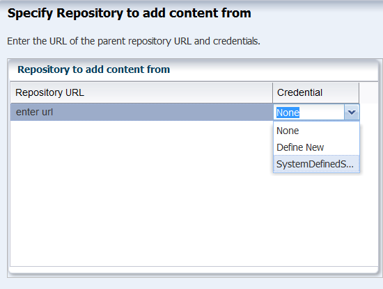
Click Add Content in the Action pane.
-
In the Repository URL field, enter the location of the file on the Enterprise Controller using the syntax:
file:///<fullpath>/post-script-paas-$<post-script-paas.version>.p5p. Complete the path and version based on your file.If credentials are required in your environment, specify the system's credentials, SystemDefinedSupportCredential.
-
When the job is completed, the file is listed in the Contents tab of the Oracle Solaris 11 Software library. To verify, open the Oracle Solaris 11 Software Library Contents tab and search for PaaS.
34.2.2 Prepare Network Resources for the vDC
Fabrics are the physical infrastructure, consisting of network interface cards and network switches. Network domains are the logical infrastructure, combining network resources from at least one fabric. The networks used by virtual assets are created from the VLAN IDs managed by a network domain. The physical fabrics support these virtual networks, through the network domain, in a manner that depends on their type. To supply network resources to a vDC, you create a network domain from an appropriate fabric.
You must have the role of Network Admin to create network domains.
34.2.2.1 Identify a Fabric
To see the available fabrics, expand Networks in the Assets pane. Select Fabrics. For each fabric, the Dashboard in the center pane includes a Management Capability field. You have these options for providing physical network resources to a new network domain:
-
Use an existing host-managed fabric.
-
Convert an unmanaged fabric to host-managed and then use it.
-
Create a new host-managed fabric.
-
Use an unmanaged fabric.
To convert an unmanaged fabric to a host-managed fabric, use the Assign VLAN ID Range action. Specify a range that matches VLANs on the isolated switch that supports the fabric. If the fabric is not supported by an isolated switch, you can use an arbitrary VLAN ID range representing configured, non-routed VLANS, for example, 1001-1200.
Perform the following steps to create a new host-managed fabric:
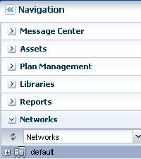
-
In the Navigation pane, navigate to Networks, then select Fabrics from the drop-down list.
-
In the Actions pane, click Define Ethernet Fabric.
-
In the wizard, enter a name in the Fabric Name field. Enter a description. Click Next
-
Enter the range of VLAN IDs. If the fabric is supported by an isolated switch, specify a range that matches the switch's VLANs. If the fabric is not supported by an isolated switch, use an arbitrary VLAN ID range, for example, 1001-1200.
-
Select the networks to be associated with the fabric, then click Next.
-
Review the Summary, then click Finish. The new fabric is host-managed
To use an unmanaged fabric, assign a set of its public networks as private networks or convert the fabric to an host-managed fabric.
34.2.2.2 Create a Network Domain
After Ops Center manages the physical fabric, its network resources are in the system-defined Default Network Domain, but you cannot use the Default network domain for a virtual datacenter. Instead, create a network domain specifically to support a server pool that contains a vDC.
A network domain is a container for networks and handles the relationship between the physical fabrics and the server pool. The fabrics provide network resources such as links and IP subnets. Within the network domain, networks that have been discovered or specified are available for assignment. These are called public networks. Their network resources have been defined. Another type of network is dynamic, that is, the network is created when it is needed, using an IP address space available to the network domain. Because they exist only for a specific purpose and only within a specific network domain, they are called private networks.
To use virtual datacenters, the network domain must provide private networks. To use existing public networks for a virtual datacenter, add each network to the network domain, making it a static private network, because existing public networks already have an IP subnet addresses and VLAN IDs.
Note:
Do not attempt to use the Default Network Domain to support a virtual datacenter. Although you are not prevented from specifying the Default Network Domain, its networks will not be available for selection.Although the network domain is providing the networks to the server pools, this is only a logical association using VLAN IDs. To use the network resources, each physical server that supports the control domains in the server pool must have a physical connection to a fabric in the network domain.
-
Expand Networks in the Navigation pane.
-
The Standard views shows Networks. The Default Network Domain is selected.
-
Click Create Network Domain in the Actions pane.
-
In the Identify Network Domain pane, enter the name and description of the network domain. You can also add tags.
-
In the Add Fabrics step, choose at least one fabric.
-
Accept the default value for the Network Creation Limit. This value is the maximum number of dynamic private networks that can be in use simultaneously and is set by the number of VLAN IDs in the range of VLAN IDs you set.
A private network uses an IP address from the pool of available IP addresses in the network domain. To exclude IP addresses that your organization is using for other purposes, specify them in the Reserved IP Address Ranges table. These addresses will not be available to dynamic private networks.
-
In the Associate Networks step, add existing networks to the new network domain. Add the network you want to use as the public network. This network will be used to provision vServers.
-
Review and click Finish.
When the job is completed, the new network domain is listed in the Navigation pane.
34.2.2.3 Configure Public Network
Select the public network and then select Edit Managed IP Ranges. Specify a range or a series of IP addresses, as provided by your network administrator. These addresses will be used later to support vServers.
34.2.3 Prepare Storage Resources
When Ops Center discovers a storage device, it creates a dynamic storage library, but these libraries cannot be used to support a vDC. Instead, create static storage libraries:
-
Create a NAS storage library to store the metadata of the control domains. This storage is exclusive for the vDC. Do not use this library for any other purpose.
-
Create at least one SAN library to store the operational data.
The storage libraries are block storage, which use Logical Unit Numbers (LUNs). The LUNs are backed by Fibre Channel disks or iSCSI disks in the form of LUNs.
SAN LUNs are associated with Fibre Channel or iSCSI target groups. Fibre Channel targets use a dedicated optical network and iSCSI targets use the IP network, but in both protocols, the targets in a target group expose one or more LUNs as a storage resource for the target's initiators.
For both protocols, Oracle Enterprise Manager Ops Center acts as the initiator. To allow the target group and Oracle Enterprise Manager Ops Center to identify each other as eligible initiators and targets, each one's Fibre Channel World Wide Number (WWN) or iSCSI IQN must be registered with the other one. Oracle Enterprise Manager Ops Center recognizes the targets because the WWNs or IQNs of the storage server are recorded when the storage server is discovered. Any LUNs that have been assigned to that WWN or IQN are eligible to be used in a storage library.
34.2.4 Create a NAS Storage Library
These are the tasks for setting up a NAS storage library:
34.2.4.1 Identify the NAS Share
The NFS share is a file system on a NAS storage device. You can view the shares on managed storage servers from the Oracle Enterprise Manager Ops Center user interface.
-
Expand Assets in the Navigation pane and click
-
Click All Assets to expand the section.
-
Click on the NAS storage server in the Storage section.
-
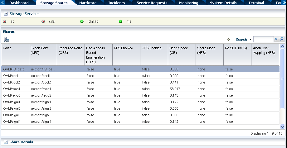
In the center pane, click the Storage Shares tab.
-
View the shares and choose one with capacity to support a server pool. You will use this share in the following procedure.
34.2.4.2 Create a NAS Storage Library
-
Expand Libraries in the Navigation pane. The new library will be created in the Filesystem Storage section.
-
Click New NAS Software Library in the Actions pane.
-
Enter a name for the library and a description. For example, identify how the new library will be used.
-
Do not associate a server pool with the new storage library. The server pool will be created later. Click Next.
-
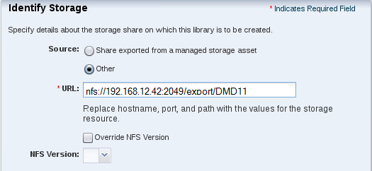
By default, the wizard displays the option for using an exported share of a storage device. Because this procedure has set up an NFS share, select Other.
-
Enter the URL or IP address for the NFS server in the URL field.
-
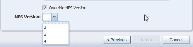
(Optional) You can specify the version of NFS that this storage uses. By default, Oracle Enterprise Manager Ops Center uses the operating system's default NFS version. To specify a different version, allow the version to be changed.
-
Select Override NFS Version.
-
Click the drop-down list of NFS versions. Select a version.
-
-
Click the Next button to review a summary of the storage library.
-
Click the Finish button to submit the job.
When the job is completed, you can see the new storage library in the Libraries section of the Navigation pane.
34.2.5 Create SAN Storage Libraries using Fibre Channel LUNs
This section describes how to set up a static block storage library, backed by Fibre Channel LUNs. The number of LUNs in the storage library determines the number of virtual hosts that the library can support
34.2.5.1 What You Will Need
You will need the following to set up and use a block storage library:
-
LUNs backed by a managed SAN server using the Fibre Channel protocol
-
The role of Storage Admin
To create LUNs on the storage server, you must have the user account and password to log into the storage server and create the LUNs as targets.
34.2.5.2 Configure the Storage Server
If you need to create LUNs and make them available to Oracle Enterprise Manager Ops Center, see the storage server's documentation for instructions in how to perform the following:
-
Configure the initiator and the targets. The initiator (Oracle Enterprise Manager Ops Center) must be able to recognize the targets (LUNs) and the targets must be able to recognize the initiator. Oracle Enterprise Manager Ops Center recognizes the targets because the WWNs of the storage server are recorded when the storage server is discovered. Any LUNs that have been assigned to that WWN are eligible to be used in a storage library. On the storage server, you must specify Oracle Enterprise Manager Ops Center's WWN as an initiator and assign LUNs to that initiator.
-
Enable multipathing on the Fibre Channel ports. Multipathing is enabled by default on Oracle Solaris x86-based systems, but is disabled by default on Oracle Solaris SPARC-based systems. Use the
stmsboot -ecommand to enable multipathing. -
Create new LUNs. It can take several hours for a new LUN to be displayed in Oracle Enterprise Manager Ops Center's user interface.
To verify iSCSI LUNs are available to the virtualization host, use the following command:
# iscsiadm list target -S
To verify Fibre Channel LUNs are available to the virtualization host, use the following command for Oracle Solaris 11:
# fcadm lu
34.2.5.3 Create a Static Block Storage SAN Library
To specify the LUNs in a storage library, you specify the server pool that will use the storage library and then select LUNs from among the LUNs available to the server pool.
-
Expand Libraries in the Navigation pane.
Figure 34-6 Storage Libraries Navigation
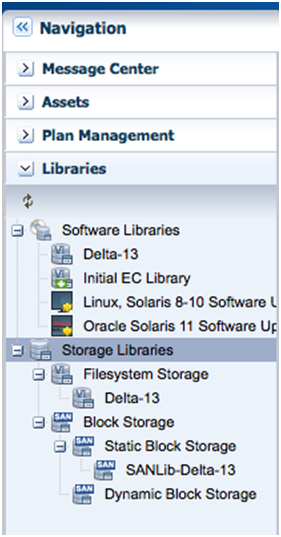
Description of ''Figure 34-6 Storage Libraries Navigation''
-
Click New SAN Storage Library in the Actions pane.
-
Enter the name and description of the library. Click Next.
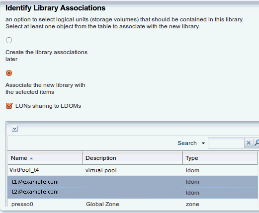
-
Select Associate the new library with the selected items and LUNs sharing to LDOMs. To create RAC instances, the SAN library must support LDom sharing in order for each logical domain to get access to its storage through any of the domains in the server pool. Click Next.
-
In the Identify LUNs step, select at least one LUN from the list of available LUNs. You can select one LUN and then add more LUNs later. Click Next.
-
Review the details of the storage library in the Summary pane. Click Finish to submit the job.
When the job is completed, the new storage library is displayed in the Libraries section of the Navigation pane in the Static Block Storage section. The center pane shows the library's Summary tab.
34.2.6 Deploy Control Domains
-
Create a Provisioning Profile for Oracle VM Server for SPARC
-
Create an OS Configuration Profile for Oracle VM Server for SPARC
34.2.6.1 Create a Provisioning Profile for Oracle VM Server for SPARC
This profile provisions the Oracle VM Server for SPARC with Oracle Solaris 11 OS. Ensure that the MSR import job is finished before creating the provisioning profile.
-
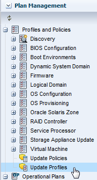
Select Plan Management section and expand Profiles and Policies in the Navigation pane.
-
Select OS Provisioning profile and click Create Profile in the Actions pane.
-
Enter the following details in the Create OS Profile - OS Provisioning wizard:
-
Name and description of the profile. In this case, the name of the profile is
control_domain_osp. -
Select
Oracle VM Server for SPARCas the Subtype andV classas the target type.
Figure 34-8 Identify Oracle VM Server Provisioning Profile
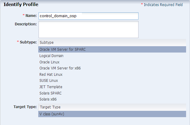
Description of ''Figure 34-8 Identify Oracle VM Server Provisioning Profile''
Click Next.
-
-
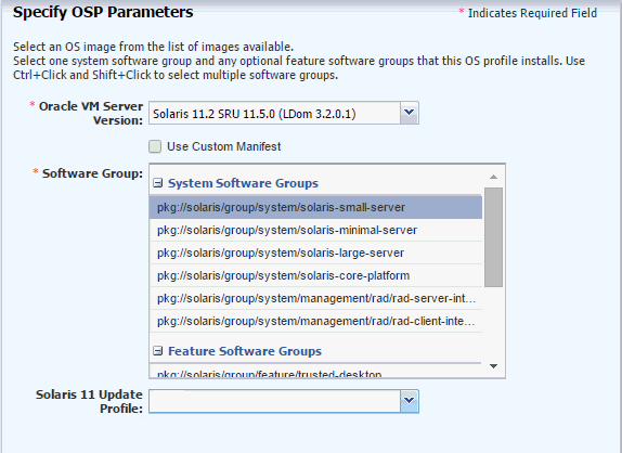
Select the Oracle Solaris and Oracle VM Server (LDom) version. Select the following parameters, then click Next:
-
For the Oracle VM Server for SPARC version, select an Oracle Solaris 11 SRU that includes your Oracle VM Server for SPARC version. For example,
Solaris 11.2 SRU 11.5.0 (LDom 3.2.0.1). If you do not see the Oracle Solaris 11 release you want, verify that the MSR import is complete or select a different Oracle Solaris 11 version that is supported by your MSR. -
For the Systems Software Group, select
solaris-small-server. If you have a complicated environment, you can choose a large server.
-
-
Keep the default values for the OS setup parameters or edit the language, time zone, and NFS4 Domain values for your environment.
-
Enter the root password and confirm the password.
-
Clear the Manual Net Boot option and the Save NVRAMRC option.
Click Next.
-
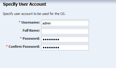
Specify the user account for logging into the control domain. Create a user account to SSH to the OS after provisioning. Provide a user name and password for the account, then click Next.
-
Do not use iSCSI disks for provisioning Oracle VM Server for SPARC. Deselect Use iSCSI Disk and click Next.
-
Edit the swap size, then click Next.
Use a minimum of 8192 MB for the swap size. The root (/) and a swap file system are defined by default but you must change the swap size, according to recommendations for sizing and performance. In general, each logical domain that this control domain supports will need 1 GB.
Figure 34-11 Specify the File System Layout
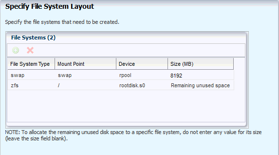
Description of ''Figure 34-11 Specify the File System Layout''
-
Select DNS as the naming service in place, and provide the details, including the server names. Naming service is not required. Click Next.
-
Review the parameters selected for the profile and click Finish to create the OS provisioning profile.
The profile appears in the center pane and in the Profiles and Policies section of Plan Management.
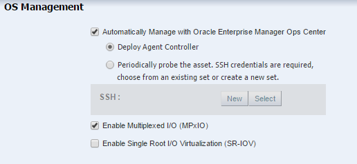
34.2.6.2 Create an OS Configuration Profile for Oracle VM Server for SPARC
The OS Configuration profile lets you define the network interface that you want to use on the operating system. The first interface you define is the boot interface and also the primary interface. You can add more than one network interface. When you apply the plan to a target, you can select which network interface is the primary interface and define the IP address.
-
Control domain configuration such as CPU Threads or Whole-cores, memory, Crypto Units, Virtual Console Port Range and Virtual Disk Server name.
-
Options such as enabling MPxIO and SR-IOV, detaching the unused buses, and saving NVRAMRC values.
-
OS management option to install the Agent Controller.
-
Networking options to use IPMP or Link Aggregation.
The recommended minimum configurations for the control domain are described in the following sections.
34.2.6.2.1 CPU Resource Allocation
The number of system CPUs determines the number of control domain CPU threads:
-
For less than 16 system CPUs, set the control domain CPU Threads to 2.
-
For between 16 and 64 system CPUs, set the control domain CPU Threads to 4.
-
For more than 64 system CPUs, set the control domain CPU Threads to 8.
You can select to allocate CPU resources either as CPU Threads or Whole-core. Whole-core is the default value in Oracle Enterprise Manager Ops Center. When you allocate as Whole-core, all the CPU Threads in the core are allocated to the control domain. For example, when you allocate two cores in UltraSPARC T2 servers, the control domain is allocated with all the 16 CPU Threads in the core. You can also set the maximum cores constraint when you select Whole-core allocation type. The maximum number of cores constraint specifies the number of cores that must be assigned to the domain.
34.2.6.2.2 Crypto Units
Crypto units are the resources on the supported platforms that provide high-performance, dedicated cryptographic engines. These can be used for tasks such as encrypting and decrypting network traffic between a Secure Socket Layer (SSL) web server and an application server.
Each CPU core has one Crypto unit and four or eight CPU threads. Because the Crypto unit is part of a core, the Crypto unit is bound only to domains that contain at least one thread from the parent core. Crypto units cannot be split as CPU threads are split. For example, you have assigned the Crypto unit for the first CPU core to the control domain. When a new logical domain is assigned a thread from the first CPU core and the Crypto unit for that core is already assigned, the control domain cannot assign that Crypto unit to the new logical domain. Allocation of Crypto units might not succeed, especially when a core is split between domains. An Oracle VM Server might allocate fewer Crypto units or none at all.
You must assign at least one Crypto unit to the control domain because the Crypto unit enables domain migration.
The use of Crypto Units is not mandatory although it might speed the logical domain migration. Allocation of Crypto Units might not be available in all the hardware.
34.2.6.2.3 RAM
The amount of RAM for the control domain depends on the size of the system RAM and the load of the system.
-
For system RAM less than 8 GB, set the control domain's RAM to 1 GB.
-
For system RAM between 8 GB to 16 GB, set the control domain's RAM to 2 GB.
-
For system RAM greater than 64 GB, set the control domain's RAM to 8 GB.
In Oracle Enterprise Manager Ops Center the default value is 4 GB as a recommended starting point for logical domains, and the minimum value is 1GB.
34.2.6.2.4 NVRAMRC Value
Automatic booting on a SPARC system uses the default boot device that is defined in the non-volatile RAM (NVRAM). User-defined commands that are executed during start-up are stored in the NVRAMRC file in the NVRAM. When you run an OS provisioning job on a SPARC machine, Oracle Enterprise Manager Ops Center resets the configuration to the factory default configuration and removes the information that is stored in the NVRAMRC file. The control domain OS configuration profile gives you the option to preserve the information in the NVRAMRC file before resetting the server to the factory defaults, and then restore the information after the reset.
To create an OS Configuration profile:
-
Select the Plan Management section and expand Profiles and Policies.
-
Select OS Configuration and click Create Profile in the Actions pane.
-
Enter a name and description in the Create Profile - OS Configuration wizard. In this case, the new profile has the name
install_cdoms_osc, select Oracle VM Server for SPARC as the Subtype, then click Next.Figure 34-12 Identify the OS Configuration Profile
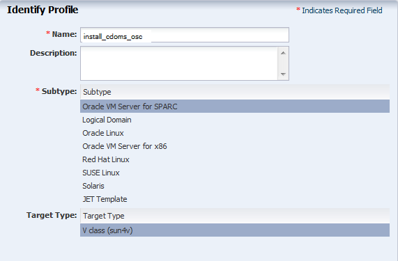
Description of ''Figure 34-12 Identify the OS Configuration Profile''
-
Select the Oracle VM Server for SPARC version to be installed. The version must match the version selected in the OS Provisioning profile.
-
Specify the resources that you want to assign to the control domain, according to the recommended minimum configuration. The control domain will route the network and Fibre Channel LUNs. Be sure to use sufficient cores and memory for your environment and control domain to avoid performance issues.
The remaining resources are then available for the logical domains.
-
CPU Model: Select Whole-core to allocate the CPU resource in cores.
-
CPU Cores: Enter the number of CPU core to be allocated to the control domain.
-
Max CPU Cores: Enter the number of CPU cores that must be assigned to control domain.
-
Memory: Enter the amount of memory required for control domain.
-
Do not provide any values for Requested Crypto Units.
-
Virtual Console Port Range: Enter the range between 5000 to 6000.
-
Keep the default name of the virtual disk server.
Clear the following options, then click Next:
-
Enable Single Root I/O Virtualization (SR-IOV)
-
Detach Unused Buses
Figure 34-13 Specify the Control Domain Parameters
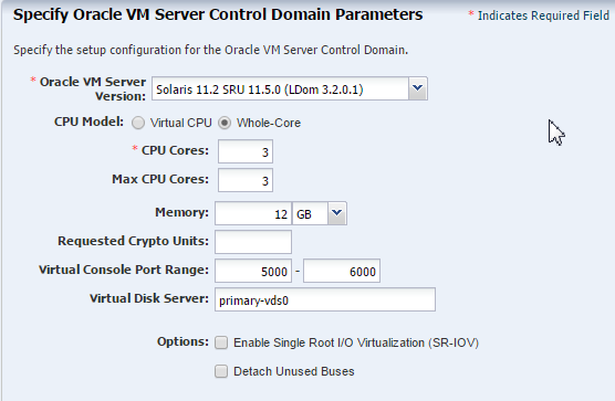
Description of ''Figure 34-13 Specify the Control Domain Parameters''
-
-
Select the option Enable Multiplexed I/O so that you can associate block storage libraries such as SAN and iSCSI for storage with the control domain. Click Next.
-
In the Specify Networking page, select None as the networking option for Oracle VM Server for SPARC. Click Next.
-
Select the network interface to use for OS provisioning. Select the Controller that hosts the network interfaces and the corresponding network interface. The Address Allocation is Use Static IP by default and cannot be modified.
Select Auto to create a virtual switch automatically for the network connection to the control domain, then click Next. The virtual switch is created in the default format. For example, the network 192.0.2.0/24, the virtual switch is created as 192.0.2.0_24.
Figure 34-14 Specify the Network Interfaces
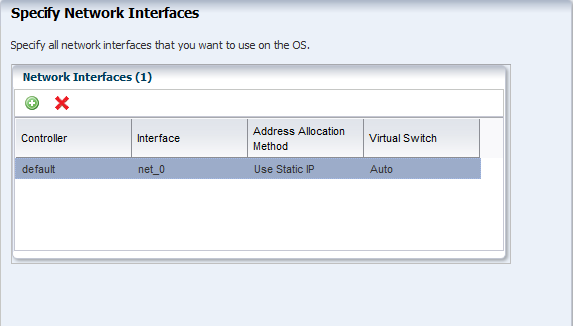
Description of ''Figure 34-14 Specify the Network Interfaces''
-
Review the parameters and click Finish to create the OS configuration profile.
The job is initiated and the new OS configuration profile appears under Profiles and Policies in the Plan Management section. You can select the OS Configuration profile to view its details in the center pane.
34.2.6.3 Create an Install Server Deployment Plan
Create an Install Server deployment plan that uses the OS provisioning and OS Configuration profiles that you just created.
-
Expand Plan Management in the Navigation pane.
-
Under Deployment Plans, select Install Server.
-
Click Create Plan from Template in the Actions pane.
-
Enter a plan name and description. For the Failure Policy, select the option to complete as much of the plan as possible.
-
Associate the profiles that you created earlier.
-
In the OS Provision step, place your cursor in the Associated Profile/Deployment Plan field for that row and select the OS Provisioning Profile you created.
-
In the OS Configuration step, place your cursor in the Associated Profile/Deployment Plan field for that row and select the OS Configuration Profile you created.
-
-
Click Save.
34.2.6.4 Apply the Install Server Deployment Plan
Apply the Install Server deployment plan to provision Oracle VM Server for SPARC.
When you apply a deployment plan to provision Oracle VM Server for SPARC, you must have the following information to complete the installation:
-
In the server hardware, obtain the network interface that is physically connected to the network that is managed by Oracle Enterprise Manager Ops Center.
-
Both tagged and untagged networks are listed for network configuration. When OpenBoot PROM (OBP) is used, only untagged networks can be used for OS provisioning as you cannot boot from a tagged network.
-
The IP address for the boot interface.
-
If you want to identify the network interface using the MAC address, you can select to enter the MAC address instead of the boot interface.
-
The details of network connection that you want to use to configure the OS after booting. For multiple network configuration, the first interface is always overwritten by the boot interface that is defined during the OS provisioning step. For single network configuration, it is same as the boot interface network.
-
Do not select the option to place the Oracle VM Server for SPARC in a server pool.
-
Select the Install Server plan in the Deployment Plans list.
-
Select Apply Deployment Plan in the Actions pane.
-
Select one or more assets and click Add to Target List.
-
Select Apply with minimal interaction. If you want to review and change the profile parameters, then select Allow me to override any profile values to verify the configuration for the OS Provisioning and OS Configuration profiles. Click Next.
-
If you selected Apply with minimal interaction, select not to review the steps that are not included in the plan and click Next.
-
The wizard collects information for provisioning Oracle VM Server for SPARC. Click Next.
-
In the Boot Interface Resource Assignments step, provide the following information:
-
Network: The network for the boot interface.
-
Controller: Select the controller that provides the network interface for OS provisioning. It is always default for the Oracle VM Server for SPARC provisioning.
-
Interface: Select the net0 interface from the list. This network interface is physically connected to the selected network.
-
IP Address: Enter the IP address for the boot interface of each target.
-
(Optional) Primary Hostname: Enter the host name for Oracle VM Server for SPARC.
If you want to identify the network interface by its MAC address, then select the option Identify Network Interface by MAC Address and enter the MAC address instead of selecting the Controller and the Interface.
Click Next to view the OS provisioning summary.
-
-
Review the parameter of OS provisioning and click Next.
-
The following steps in the wizard collects information about OS configuration.
Click Next.
-
Specify the network resources that were defined in the profile. Select the network and for each network, select the network interface and enter the IP address.
The first network interface listed is the boot interface. For multiple network configuration, the first network interface is always overwritten by the boot interface network. You can select which is the primary network interface after the provisioning of the OS.
For single network, the boot interface network will be the defined as the primary network during OS configuration.
Click Next.
-
Select the option Do not assign to a Server Pool. Click Next.
-
Review the summary of the OS configuration parameters and click Next to schedule the job.
-
Schedule the provisioning job to run Now. Click Apply to apply the deployment plan on the selected targets.
When the job completes, the control domain is installed and appears in the All Assets section and each is managed by an Oracle VM Server for SPARC agent.
34.2.7 Create the Server Pool
A server pool is a group of control domains that has access to the same virtual and physical networks and storage resources. Server pools provide load balancing, high availability capabilities, and sharing of the resources for all the members of the pool.
This procedure creates a server pool containing the control domains you created, both storage libraries you created, and the network domain you created.
Before you begin, you must know the network interface that is the physical connection to the system that supports the control domain.
-
Select Server Pools in the Resource Management View of the Navigation pane.
-
Click Create Server Pool in the Actions pane.
-
Enter a name and description for the server pool.
-
Select Oracle VM Server - SPARC from the Virtualization Technology list.
-
Click Next.
-
Select the Oracle VM Servers to be added to the server pool. Click Next.
Figure 34-15 Select Members of the Server Pool
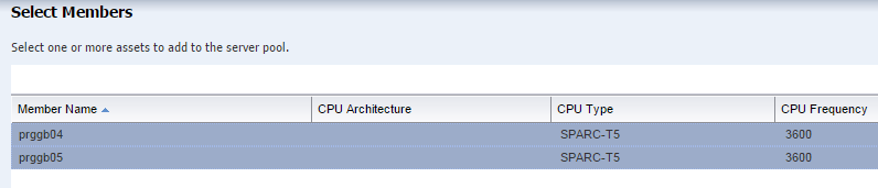
Description of ''Figure 34-15 Select Members of the Server Pool''
-
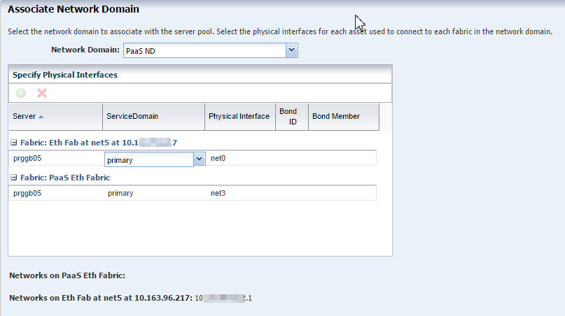
Select the new network domain to be associated with the server pool. When you select a the network domain, the Specify Physical Interface table is populated with the fabrics in the network domain.
-
Specify how each fabric connects to each Oracle VM Server, then click Next.
Note:
In the Physical Interface column, for each Oracle VM Server, select the name of the NIC that the system that hosts the Oracle VM Server uses to connect to the fabric. The NIC that is displayed initially is not a default; you must specify the NIC to use. Make sure that the proper interfaces are selected. If the public network is wrong, you cannot create virtual servers. If the private fabric connections are wrong, you cannot create attached private networks. -
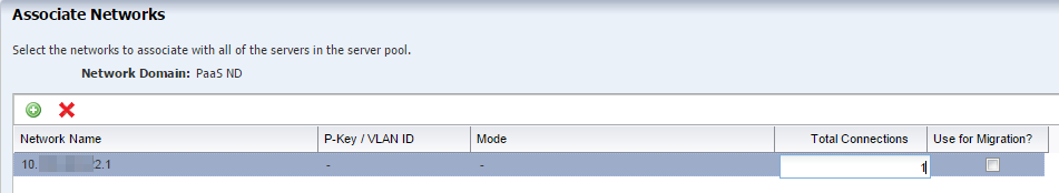
Click the Add Network icon to associate the public network in the network domain with the servers in the server pool. Enter 1 as the number of connections to the network in the Total Connections field. If you have pre-defined private networks managed outside of Enterprise Manager Ops Center, you can add them here. Click Next.
-
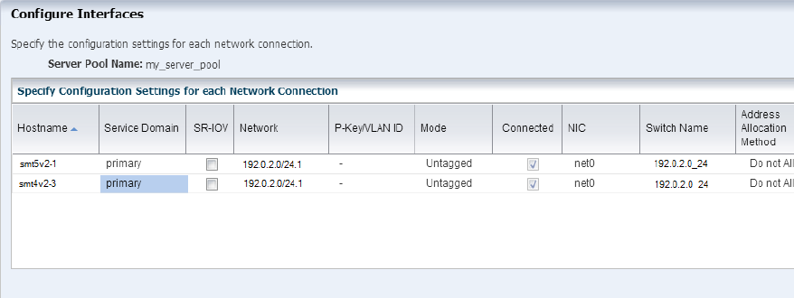
Specify the network configuration settings for each Oracle VM Server. If you correctly deployed the control domain, the information in the Configure Interfaces is correctly completed and the Oracle VM Server is already connected to the selected network. The UI displays the existing connection details to the network.
The following are the interfaces for each fabric in the network domain:
-
For the fabric that supports the public network (the routable network), select any existing interfaces to the control domain. If no interface has been connected to the control domain, select the interface that is connected to the Ethernet switch.
-
For the host-managed fabric, select the interface that is connected to Ethernet switch. Do not use bonded interfaces. Click Next.
Note:
In the NIC column, for each Oracle VM Server, select the name of the NIC that the system that hosts the Oracle VM Server uses to connect to the fabric. Specify the same NIC that you chose in Step 8. -
-
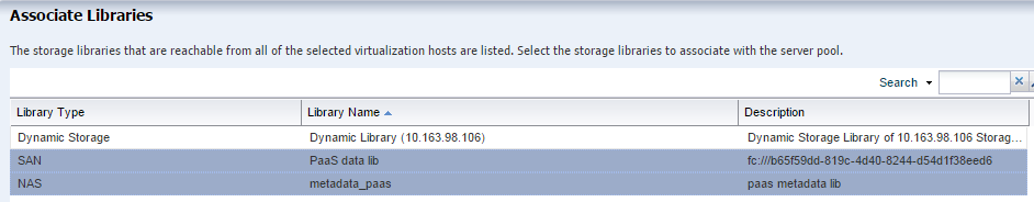
Storage libraries that are reachable from the selected members of the pool are displayed. Select the NAS and the SAN storage library to be associated with the server pool. Do not select a dynamic storage library. Click Next.
-
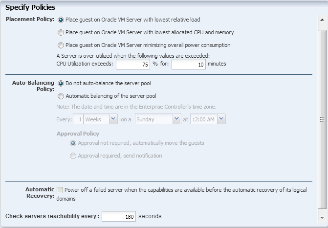
Select the placement and auto balancing policy, then click Next:
-
Place the guest on Oracle VM Server with lowest relative load. The vDC will override this placement policy.
-
Do not auto balance the server pool.
-
Clear the option for Automatic Recovery. Enterprise Manager Cloud Control will take control of the high availability.
-
-
Review the server pool information, then click Finish to create the server pool.
When the job finishes, the server pool is created and appears in the Server Pools view of the Assets section. Open the job to confirm that the job completed successfully.
34.2.8 Refresh the Library
Before you create the vDC, refresh the Static Block Storage Library. If the number is not refreshed before creating the vDC, it will break provisioning.
-
Expand Libraries, then expand Storage Libraries in the Navigation pane.
-
Select the storage library under Static Block Storage.
-
Click the Refresh button at the top of the center pane.
Wait a few minutes before creating the vDC to ensure that the refresh is complete. Refresh does not launch a job and you do not receive any notification that the library is refreshed.
34.3 Set Up and Configure a Virtual Data Center
34.3.1 Create an Enterprise Manager User
Add a user to connect Enterprise Manager Ops Center with Enterprise Manager Cloud Control. The user does not need to have full access to Enterprise Manager Ops Center, only the Cloud role. You can create a local user or use a naming service.
You must have the Enterprise Manager Ops Center User Admin role to add a user.
-
Select Administration in the Navigation pane.
-
Click Local Users.
-
Click the Add User icon.
-
Enter
ocadminas the user name. -
Add the Cloud role to the list of Selected Roles. You can add other roles, but it is not required. Click Add User.
34.3.2 Create the vDC
The vDC inherits network resources and storage resources from the server pool. The vDC enables cloud users to create virtual machines and run applications. The cloud user provides networking to its virtual machines from the public networks that are allocated to each account or by creating private networks. The cloud user can use the public networks, or create a private vNet for use in the account. When the cloud users create a private vNet, either a dynamic private network is created or the static private network is available for use in that account.
You must have the Enterprise Manager Ops Center Cloud Admin role to create a vDC.
-
Select vDC Management in the Navigation pane.
-
Click Create Virtual Datacenter in the Actions pane.
-
The first step Create Virtual Datacenter Wizard is an introduction to the vDC and the prerequisites for creating a vDC. Click Next.
-
In Specify Virtual Datacenter Details:
-
Provide a name and description for the vDC.
-
Enter tags to distinguish this vDC from other vDCs.
-
Select Password Required to enforce using credentials when creating vServers in the vDC. When this option is enabled, cloud users must specify a root password, with or without an SSH key. In addition, cloud users must specify either an SSH key or remote user credentials when creating vServers that use Oracle Solaris 11 OS.
Click Next.
-
-
Select the new server pool from the list.
If the server pool does not appear in the list, the server pool was not properly configured. Ensure that the metadata library is created and that there is a dedicated network domain. The vDC is homogeneous. You can only add compatible server pools that have Oracle VM Server for SPARC. It is recommended to not mix machines that have different CPU and memory configurations.
-
Select one or more boot networks from the public network. You must select at least one network.
Note:
Boot networks are required for vServer OS deployment. You must also add at least one boot network to each account in the vDC for creating vServers in the account. You can also assign a boot network to an account and use it as a public network for that account.Click Next.
-
The vCPU sizing displays this information:
-
Total number of vCPUs: The total number of vCPU in the vDC for the updated vCPU to physical CPU Threads ratio.
-
Avg memory per vCPU: The average memory per vCPU in GB. The total memory available for the vDC by the total number of vCPUs. When you want to use the CPU and memory resources to the full extent, the vServers must use this amount of resources.
Accept the default values and click Next.
-
-
Select Static Block Storage Libraries as the storage type for the root disk.
-
Select the SAN storage library you created.
-
Select Static Block Storage Libraries as the storage type for the volume and.
-
Select the SAN storage library you created.
Click Next.
-
Confirm the vDC configuration and click Finish to create the vDC. The vServers will run in this vDC, according to the vServer type.
34.3.3 Create the vDC Account for PaaS
In creating the account, you allocate resources from the vDC to the account. The resource allocation for all the accounts in a vDC can be more than the actual resources in a vDC. This oversubscription of the resources must be planned. You must update the resources when the requirement increases.
-
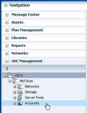
Expand vDC Management on the Navigation pane.
-
Expand vDCs, select the new vDC, then click Accounts.
-
On the Actions pane, click Create Account.
-
Enter the name for the account:
PaaS_Account, then click Next. -
Specify the quotas of vCPU, Memory, and Storage for the account.
Only one account will control the resources. For this
PaaS_Account, specify the maximum capacity of each resource.In the Number of private vNets field, enter the number of private vNets for this account, which is the same as the number of VLAN IDs assigned. Click Next.
Figure 34-22 Specify Account Resource Limits
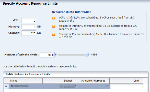
Description of ''Figure 34-22 Specify Account Resource Limits''
-
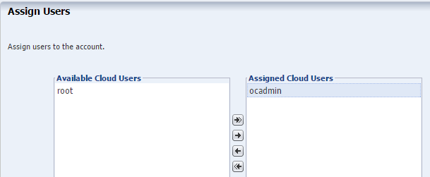
Select the Enterprise Manager Ops Center user with the Cloud role,
ocadmin, that you created earlier. Use the right arrow key to add this user to the list of Assigned Cloud Users. Do not assign therootuser. Click Next.The
ocadminuser is the connection between Enterprise Manager Ops Center and Enterprise Manager Cloud Control. Cloud Control will connect to Ops Center using this user account. -
View the Summary and click Finish to create the account. When the job is completed, a new account is created.
34.3.4 Prepare the vServers
A vServer is an entity that provides the outward interface of a stand-alone operating system that consumes CPU, storage, and memory resources. A vServer has its own identity, local storage, interfaces, and configuration that exist for the full lifetime of the vServer. You determine the creation of new vServers according to the account quota limits and applications requirements.
When creating a vServer, the following account resources are required:
-
A vServer type: vServer Types are profiles that define the computing resources such as virtual CPU, memory, and storage size. You select the best suitable vServer type from those available for the account. vServer types are visible to cloud users during the vServer creation process.
-
A server template: Server templates designate the OS provisioning and OS configuration for the vServer. You can either select a server template from those that exist for the account or create a new server template.
-
One or more virtual networks: For the vServer network connectivity you must choose one or more vNets from the available vNets or create new ones before creating a vServer. vServers are only assigned to virtual networks when the vServer is created.
34.3.4.1 Create a New vServer Type
When you create a vServer type, the VM hosting details display the following information in the wizard based on the resources defined:
-
The number of virtualization servers in the vDC that have sufficient physical resources to host a vServer with the selected resources.
-
An estimation of number of vServers that can be hosted with the total number of physical resources of the vDC.
-
A warning when the current value of the memory size exceeds the selected storage size.
-
Select the vDC and click Create vServer Type in the Actions pane.
-
Provide a name and description to identify the type. For example:
-
single instance DBAAS -
RAC instance DBAAS -
RAC big instance DBAAS
-
-
Add tags for identification and classification of the vServer type. Click Next.
-
Specify values for vCPU, memory and storage resources, then click Next.
The VM Hosting Details will display the estimated number of vServers that can be hosted based on the figures you supply. The minimum amount of RAM for Oracle Solaris 11.2 is 2 GB. For example, Table 34-1 shows the recommended values for the DBaaS instances deploying Oracle 12c Database.
-
Review the information provided and click Finish to create the vServer type.
34.3.4.2 Create a Private vNet
Private vNet is a private virtual network set up exclusively for an account. The vServers associated with this vNet have private virtual IP address for internal communication. In this PaaS solution, only RAC instances use private networks. Generally, the number of networks is equal to the number of real application clusters that you want to host on your cloud. The private networks are used as the cluster interconnect, but you can use them to connect different virtual machines between each other with a network that cannot see them from the public network.
-
Expand vDC Management on the Navigation pane.
-
Expand vDCs, select the new vDC, then click Accounts.
-
Select the account you created.
-
On the Actions pane, click Create Private vNet.
-
Enter the name and description for the private virtual network. For example, large_private_vnet or small_private_vnet. Click Next.
-
Use the slide bar to set the value of the number of elements, or hosts. Click Next.
The values entered are rounded up to the next value of 13, 29, 61, 125, 253, 509, 1021, 2045, 4093, and 8189. Do not use the values of 1 or 5. You cannot change the size of a network after it is created so specify the size needed to accommodate your current and future requirements:
-
The number of elements is also the maximum number of vServers that can be part of this vNet. Class C networks (for example, 10.0.0.1/24) enable you to create 256 vServers and Class 16C networks (for example, 10.0.0.2/20) enable you to create 4096 vServers.
-
Whether the vNets will be shared or dedicated. If multiple RAC instances will share one or more networks, set the network size to 509 and more. If each RAC instance will have a dedicated network, limit the network size to 29 or 13.
-
-
Review the Summary, then click Finish to create the private virtual network.
The new private virtual network is listed in the Networks and vDC sections of the Navigation pane.
Figure 34-25 View of the New Private Virtual Network
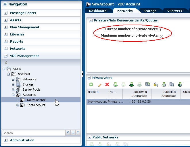
Description of ''Figure 34-25 View of the New Private Virtual Network''
-
Connect the IP address from this new private virtual network to the vServer, using Connect Private vNet icon in the Private vNets table. Click Connect.
Note:
If you have multiple vNets, connect each vNet one at a time. Wait for each job to complete before making the next connection.

34.4 Set Up and Configure a Server Template
Before you can create guest domains, you must create the necessary profiles and plans to define the operating system for the guest. After you create the profiles you will create a Server Template to apply the profiles.
Server Templates are a combination of OS update, OS provisioning, and OS Configuration profiles.You can create several profiles and server templates.
34.4.1 Create an OS Update Profile
The Oracle Solaris 11 OS Update profile installs packages as part of an OS Provisioning profile. This example shows how to create an OS Update profile that installs the integration package. You then add this profile to an OS Provisioning profile.
-
Expand Plan Management in the Navigation pane, then select Update Profiles under Profiles and Policies.
-
Click New Profile in the Actions pane.
-
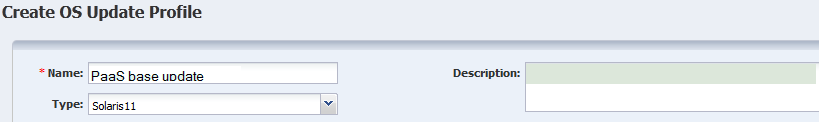
Enter a name and description for the profile. In this case, the profile is
PaaS base update. Then select Solaris 11 from the Type menu. -
Keep the default filters and then search for each one of the following packages and files and click the Install icon. If more than one version appears, select the latest version.
-
SUNWhea
-
SUNWsprot -
developer/assembler -
developer/java/jdk-6 -
developer/java/jdk-7 -
post-script-paas
-
-
Click Create OS Update Profile. The profile appears in the list of Update profiles.
34.4.2 Create an OS Provisioning Profile for Guests
The OS provisioning profile will define the operating system image and PaaS package to install on the guest. This example installs Oracle Solaris 11.2 SRU 11.5.0.
Perform the following steps to create a new OS Provisioning profile:
-
Select the Plan Management section in the Navigation pane.
-
Expand Profiles and Policies and select OS Provisioning profile.
-
Click Create Profile in the Actions pane.
The Create Profile - OS Provisioning wizard is displayed.
-
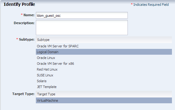
Provide the following details for the profile identification, then click Next:
-
Enter the name of the profile as ldom_guest_osp.
-
Enter a suitable description for the profile that describes the OS.
-
Select Logical Domain as the Subtype and Virtual Machine as the Target Type.
Figure 34-28 Identify the Logical Domain Profile
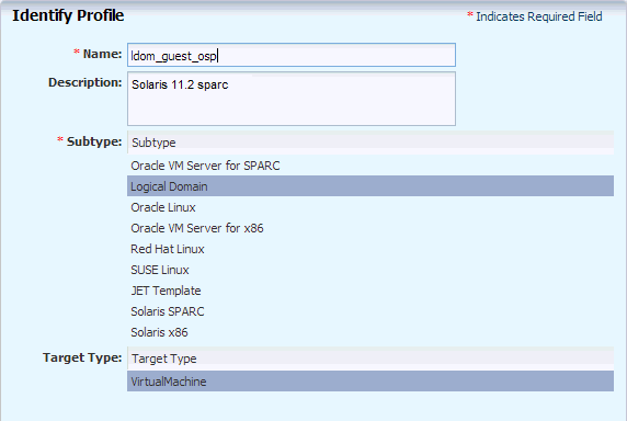
Description of ''Figure 34-28 Identify the Logical Domain Profile''
-
-
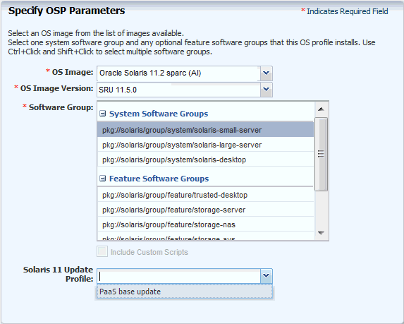
Select the following OSP parameters:
-
The Oracle Solaris 11.1 OS and the SRU from the list.
-
solaris-small-serveras the Software Group from the list. -
For the Solaris 11 Update profile, select the OS Update Profile that you created:
PaaS base update.
Click Next to specify the OS Setup.
-
-
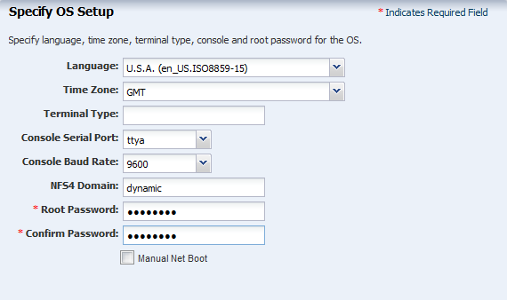
Specify the OS setup parameters, then click Next:
-
Enter the time zone, language, terminal type, console serial port, and console baud rate.
-
Enter the root password. The password that you enter here will be overwritten. Cloud Control will deploy its own password.
-
The NFS4 domain is set to dynamic in this example. If a naming service is configured in your environment, enter the NFS4 domain value.
-
-
In the Specify User Account page, enter a user name and password to create a user account, then click Next.
Note:
Cloud Control will overwrite this password and deploy its own password. -
(Optional) If you want to use iSCSI disks for OS provisioning, select the check box. Click Next.
Figure 34-31 Specify if an iSCSI Disk is to be Used for Provisioning
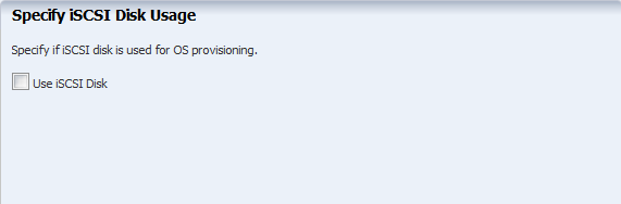
Description of ''Figure 34-31 Specify if an iSCSI Disk is to be Used for Provisioning''
-
The root (/) and a swap file system are defined by default. You can change the swap size. Click the Add icon to add more ZFS file systems. Click Next to specify the name service.
Note:
The minimum swap space should be 6 GB. If you are using a larger deployment, you might increase the swap or create multiple server templates.Figure 34-32 Specify the File System Layout
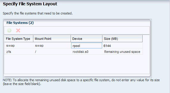
Description of ''Figure 34-32 Specify the File System Layout''
-
Select the DNS naming service, then click Next.
Note:
Ensure that your DNS naming service is working and that it conforms to public network requirements. All public IPs must be resolvable by the naming service. -
Review the parameters selected for the profile and click Finish to create the OS provisioning profile.
The OS provisioning profile is created and listed under the OS provisioning profiles. Use this profile to create a Provision OS plan.
34.4.3 Create an OS Configuration Profile for Guests
-
Select the Plan Management section and expand Profiles and Policies.
-
Select OS Configuration and click Create Profile in the Actions pane.
-
Enter the following details to identify the profile, then click Next:
-
Name and description of the profile.
-
Select Logical Domain as the Subtype and Virtual Machine as the Target Type.
Figure 34-33 Identify the OS Configuration Profile for the Guests
Description of ''Figure 34-33 Identify the OS Configuration Profile for the Guests''
-
-
Select Automatically manage with Oracle Enterprise Manager Ops Center and Deploy the Agent Controller. To manage the virtual machines, you can select the option Enable Multiplexed I/O so that you can associate block storage libraries such as FC and iSCSI for storage with the OS. MPxIO is not required because the control domain will control the management.
Deselect the option Enable Single Root I/O Virtualization (SR-IOV), the option is only applicable to root domains. Click Next.
-
In Specify Networking, select None as the networking option for the OS, then click Next.
-
Enter 1 in the network interfaces field. The vDC will create the network interfaces and overwrite this value. Click Next.
-
Review the parameters and click Finish to create the OS configuration profile.
34.4.4 Create a vServer Template
Create a vServer template from the new OS profiles you created: provisioning, which includes the update profile, and configuration. You can create different templates for different profiles and deployments.
-
Select the account in the vDC Management section.
-
Click Create Server Template in the Actions pane.
-
In the wizard, skip the introduction and click Next.
-
Enter the name and description for the server template. Click Next.
-
Select the new OS provisioning profile, then click Next.
-
Select the new OS configuration profile from the list, then click Next.
-
Review the information and click Finish to create the server template.
The new template is created and available to create vServers.
34.4.5 Create a vServer
Use the Server Template to create one or more vServers.
-
Select the account in the vDC Management section.
-
Click Create Server in the Actions pane.
-
In the wizard, skip the introduction and click Next.
-
Enter the name and description for the server.
Click Next.
-
Select the new OS provisioning profile, then click Next.
-
Select the new OS configuration profile from the list, then click Next.
-
Review the information and click Finish to create the server.
34.5 Validate the Integration and PaaS
Test the connections from Enterprise Manager Cloud Control and Enterprise Manager Ops Center as the cloud user. In this test, create two vServers with the same storage and network resources. If successful, one vServer can send information to and receive information from the other vServer. To test, log out as the Admin user and log in as the cloud user.
34.5.1 Create Volumes for vServer
Use the following procedure to create volumes from shared disks. In normal operations, Enterprise Manager creates the volumes.
-
Expand vDC Management in the Navigation pane.
-
Select the account from the vDC Accounts list.
-
Click Create Volume in the Actions pane.
-
Enter a name for the volume, then click Next.
-
Check the Shared option and enter the size of the volume. Click Next.
-
Click Finish to create the volume.
Delete the volume when the job has completed.
34.5.2 Create Test vServers
Create two vServers with the same private network.
-
Expand vDC Management in the Navigation pane.
-
Select the account from the vDC Accounts list.
-
Click Create vServer in the Actions pane.
The Create vServer Wizard is displayed.
-
Enter the following information in the vServer Details step:
-
Name and description for the vServer.
-
Tags for better identification and classification of the vServer.
-
Number of vServers to create.
-
The High Availability Support option has no effect in the PaaS integration.
Click Next.
-
-
Select a server template from the list. Click Next.
-
Select a vServer type from the list. Click Next.
-
Select one or more volumes from the Available Volumes list. Use the arrow keys to move the selected volumes to the Attached Volumes list.
For this test, attach the same volume to both vServers.
Click Next.
-
Select one or more vNets from the list. Click Next.
-
Select the Static method for assigning the IP address.
-
Assign the IP address from the new private virtual network to the vServer. Click Next.
You can also perform this step after you create the vServer by clicking the Connect vNet icon on the account's Networks tab in the Private vNet table.
Do not select a distribution group. Click Next.
-
Specify a root password. Click Next.
-
Confirm the vServer information provided in the Summary and click Finish to launch the job to create the vServer.
After the job completes, the vServer is created and listed in the Navigation pane. By default, the DNS and other naming information is taken from the selected vNet or server template and added in the
/etc/resolv.conffile of the vServer.
34.5.3 Verify Shared Storage and Connectivity
To verify connectivity of the two vServers. From the console, log into one vServer and use the ping command with the IP address of the other vServer. This succeeds on public network or private network.
To verify shared storage:
-
For a Fibre Channel SAN storage:
fcadm lu -
For iSCSI SAN storage:
iscsiadm list target -S
The Client Kit also contains the new_vDC.ksh script that can be useful for diagnosing problems. Enterprise Manager uses the file when it starts the integration, using the file path /tmp/INPUT/bootstrap.xml but you can also perform this manually.
Note:
After you finish testing, delete thebootstrap.xml file and the oc-pass.txt files because they contain security information such as passwords and URLs.-
Create a file named
bootstrap.xmlin the following form and using your site's information.<bootStrap version="1.0" name="boot_strap" xmlns:xsi="http://www.w3.org/2001/XMLSchema-instance" xsi:noNamespaceSchemaLocation="bootstrap.xsd"> <!-- Ops-center details required to establish connection before running the ops center commands --> <opsCenterDetails> <opsCenterURL>https://<yourhostname>.com</opsCenterURL> <!-- OpsCenter credentials --> <opsCenterUser>ocadmin</opsCenterUser> <opsCenterHome>/opt/oracle/iaas/cli/</opsCenterHome> <!-- Stage location on Ops Center Host --> <opsCenterStageLoc>/tmp/</opsCenterStageLoc> </opsCenterDetails> </bootStrap> -
Issue the following commands:
-bash-4.1$ echo password > /tmp/INPUT/oc-pass.txt
-bash-4.1$ /opt/oracle/paas/tools/new_vDC.ksh
-
Review the output:
Certificate added to truststore /export/home/ocadmin/.oracle_iaas/truststore
Vserver types
4159 EXTRA_LARGE Logical Domain extra-large instance type for vDC PaaS_vDC 17179869184 28          4
4158 LARGE       Logical Domain large instance type for vDC PaaS_vDC       8589934592  24          2
4157 SMALL       Logical Domain small instance type for vDC PaaS_vDC       4294967296  20          1
4161 paas_RAC                                                              12884901888 45          16
4160 paas_SI                                                               4294967296  45          16
Vnets
VNET-321a93e4-2d11-4642-b3ec-3ebde6e86b04 big_private_net  big_private_net OK     172.16.0.0/20  private
VNET-badc34e5-021a-44c7-a7ad-d11915e04ec3 small_rac_net1   small_rac_net1  OK     192.168.0.0/28 private
VNET-47f06e55-7c72-4116-919f-bb940c978b8a 10.163.96.0/22.1                 OK     1x.16x.x6.0/22 public_external
Vserver s
TMPL-116826d2-6a96-4217-ab16-0d4a71157028 paas_default             OK     12884901888 false            false
34.5.4 Diagnosing Problems
If a virtual datacenter is unable to create vNets, edit the network domain to increase the limit of private networks it can provide simultaneously.
If the control domain is already running and you change the fabric that supports the server pool, you will need to configure the Fibre Channel controller:
-
fcadm hba-port -
Identify active ports.
-
fcadm remote-port -p <each_portID_from_output> -
# cfgadm -c configure <controller_to_be_configured>