14 Work with Data Modeling
This chapter contains these topics:
14.1 Working with Data Modeling
The Data Modeling feature provides graphic representation of the relationships of different files. The important aspects of the JD Edwards World Data Modeling feature are:
-
It is graphical in its presentation.
-
It allows you to narrow the amount of information you view so you can better analyze the file and data relationships.
-
It is integrated back to the Data Dictionary and other cross reference tools.
Note:
To create a data model, you must run the Data Model rebuild, P9804DM from the DREAM Writer version list.14.2 Accessing Data Modeling
-
Use one of the following methods to access Data Modeling.
-
Inquire on the file through Software Versions Repository (SVR) and press F23.
-
Type the menu selection on the command line and press F23.
-
From the Model Relations form (G9241), select Data Modeling.
Figure 14-1 Data Model Diagrammer Message screen.

Description of "Figure 14-1 Data Model Diagrammer Message screen."
-
-
Press F6 to continue.
The Data Modeling form displays with the cursor positioned in the field where you enter a file name.
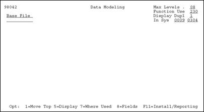
Figure 14-2 Data Modeling screen (part 1)

Description of "Figure 14-2 Data Modeling screen (part 1)"
-
To view the Data Model, enter a file name and press Enter.
Field Explanation Max Levels Determines what level of detail you want to view in terms of file relationships. Level 1 represents the highest level and level 10 represents the lowest level. The default value is level 08. Level 01 shows only those files that are directly related to the data model file. Function Use Displays the files that either match or have a function use less than the function use you specify. Display Duplicate Relationships Determines whether you want to display duplicate relationships or not. The valid values are: 1 – No duplicates (default value)
2 – First logical only
3 – All files
In Sys Limits your model to only those files from the specified install or reporting system codes. To toggle to reporting system codes, you press F11, Install/Reporting. -
To narrow the amount of file information displayed, specify values in the four fields appearing in the upper right of the form.
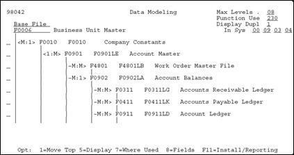
Figure 14-3 Data Modeling screen (part 2)

Description of "Figure 14-3 Data Modeling screen (part 2)"
14.2.1 Detailed Explanation of a Line
The following figure shows a portion of the Data Modeling form.
Figure 14-4 A Portion of the Data Modeling screen

Description of "Figure 14-4 A Portion of the Data Modeling screen"
Below is an explanation of the components displayed on the form.
-
Business Unit Master is the primary file (F0006)
-
Company Constants is the secondary file (F0010)
-
<m:1> - There is a many to one, bi-directional relation between the files
14.2.2 Function Key Exits from Data Modeling
| Function Key | Description |
|---|---|
| F11 | Install/Reporting
Allows you to toggle between displaying install or reporting system codes. |
| F16 | Rebuild A File Relationship
Exits to a DREAM Writer versions list. The rebuild is fundamentally based upon the program finding a connection between data items. For example, if you create new data items in the Data Dictionary and use those data items when creating a new file, you do not get a graphic representation for that file because the data items do not exist in any other file. To create and present file relationships, there must be at least one data item in the primary file that also resides in some other file as well. Print the Data Model |
| F21 | Print the Data Model
Prints the current data model |
14.2.3 Selection Exits from Data Modeling
| Option | Description |
|---|---|
| 1 | Move Top To select a file in the current data model and move it to the top to view its data model. |
| 5 | Display To view the file relationships. The Define a File Relationship form displays the relationship detail for the two files. |
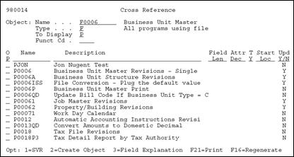
| 7 | Where Used Exits to the Object Cross Reference Repository and displays all the programs that access the particular file. |
| 8 | Fields To access the File Field Description form for any file displayed in the Data Model. The File Field Description form presents all the fields in a file, the field type, their size and their position in the file. |

