| Skip Navigation Links | |
| Exit Print View | |

|
Managing Oracle Solaris 11.1 Network Performance Oracle Solaris 11.1 Information Library |
| Skip Navigation Links | |
| Exit Print View | |

|
Managing Oracle Solaris 11.1 Network Performance Oracle Solaris 11.1 Information Library |
1. Introduction to Network Performance Management
4. Administering Bridged Networks (Tasks)
7. Exchanging Network Connectivity Information With LLDP
8. Working With Data Center Bridging Features in Oracle Solaris
9. Edge Virtual Bridging in Oracle Solaris
10. Integrated Load Balancer (Overview)
11. Configuring Integrated Load Balancer
Importing and Exporting Configurations
Configuring ILB for High-Availability (Active-Passive Mode Only)
Configuring ILB for High-Availability Using the DSR Topology
How to Configure ILB to Achieve High-Availability by Using the DSR Topology
Configuring ILB for High-Availability Using the Half-NAT Topology
How to Configure ILB to Achieve High-Availability by Using the Half-NAT Topology
12. Managing Integrated Load Balancer
13. Virtual Router Redundancy Protocol (Overview)
A. Link Aggregation Types: Feature Comparison
This section describes the high-availability (HA) configuration of ILB using the DSR, half-NAT topologies.
This section describes how to set up the ILB connections to achieve high availability (HA) by using the DSR topology. You need to set up two load balancers, one as the primary load balancer and the other as the standby load balancer. If the primary load balancer fails, the standby load balancer assumes the role of the primary load balancer.
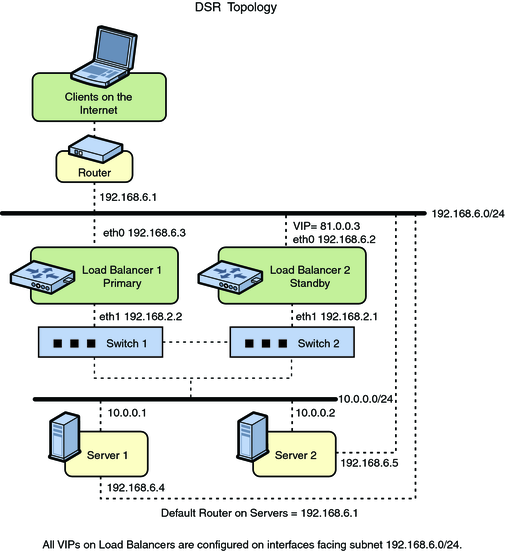
The following figure shows the DSR topology for configuring the ILB connections to achieve HA.
Figure 11-1 ILB for HA Configuration Using DSR Topology

You can assign the ILB Management rights profile to a role that you create. To create the role and assign the role to a user, see Initially Configuring RBAC (Task Map) in Oracle Solaris 11.1 Administration: Security Services.
# ilbadm create-servergroup -s server=10.0.0.1,10.0.0.2 sg1
# ilbadm create-rule -i vip=81.0.0.3,port=9001 \
-m lbalg=hash-ip-port,type=DSR -o servergroup=sg1 rule1
Server1# ipadm create-addr -d -a 81.0.0.3/24 lo0
Server2# ipadm create-addr -d -a 81.0.0.3/24 lo0
LB1# dladm create-vnic -m vrrp -V 1 -A inet -l eth0 vnic1
LB1# vrrpadm create-router -V 1 -A inet -l eth0 -p 255 vrrp1
LB1# ipadm create-addr -d -a 81.0.0.3/24 vnic1
LB2# dladm create-vnic -m vrrp -V 1 -A inet -l eth0 vnic1
LB2# vrrpadm create-router -V 1 -A inet -l eth0 -p 100 vrrp1
LB2# ipadm create-addr -d -a 81.0.0.3/24 vincl
The preceding configuration provides protection against the following failure scenarios:
If Load Balancer 1 fails, Load Balancer 2 becomes the primary load balancer. Load balancer 2 then takes over address resolution for the VIP 81.0.0.3 and handles all the packets from clients with the destination IP address 81.0.0.3.
When Load Balancer 1 recovers, Load Balancer 2 returns to standby mode.
If one or both of Load Balancer 1's interfaces fails, Load Balancer 2 takes over as the primary load balancer. Load Balancer 2 then takes over address resolution for VIP 81.0.0.3 and handles all the packets from clients with the destination IP address 81.0.0.3.
When both of Load Balancer 1's interfaces are healthy, Load Balancer 2 returns to standby mode.
This section describes how to set up the ILB connections to achieve high availability (HA) by using the half-NAT topology. You need to set up two load balancers, one as the primary and the other as the standby. If the primary load balancer fails, the standby load balancer assumes the role of the primary load balancer.
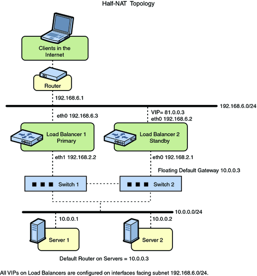
The following figure shows the half-NAT topology for configuring the ILB connections to achieve HA.
Figure 11-2 ILB for HA Configuration Using Half-NAT Topology

You can assign the ILB Management rights profile to a role that you create. To create the role and assign the role to a user, see Initially Configuring RBAC (Task Map) in Oracle Solaris 11.1 Administration: Security Services.
# ilbadm create servergroup -s server=10.0.0.1,10.0.0.2 sg1
# ilbadm create-rule -ep -i vip=81.0.0.3,port=9001-9006,protocol=udp \
-m lbalg=roundrobin,type=HALF-NAT,pmask=24 \
-h hc-name=hc1,hc-port=9006 \
-t conn-drain=70,nat-timeout=70,persist-timeout=70 -o servergroup=sg1 rule1
LB1# dladm create-vnic -m vrrp -V 1 -A inet -l eth0 vnic1
LB1# ipadm create-addr -d -a 81.0.0.3/24 vnic1
LB1# vrrpadm create-router -V 1 -A inet -l eth0 -p 255 vrrp1
LB1# dladm create-vnic -m vrrp -V 2 -A inet -l eth1 vnic2
LB1# ipadm create-addr -d -a 10.0.0.3/24 vnic2
LB1# vrrpadm create-router -V 2 -A inet -l eth1 -p 255 vrrp2
LB2# dladm create-vnic -m vrrp -V 1 -A inet -l eth0 vnic1
LB2# ipadm create-addr -d -a 81.0.0.3/24 vnic1
LB2# vrrpadm create-router -V 1 -A inet -l eth0 -p 100 vrrp1
LB2# dladm create-vnic -m vrrp -V 2 -A inet -l eth1 vnic2
LB2# ipadm create-addr -d -a 10.0.0.3/24 vnic2
LB2# vrrpadm create-router -V 2 -A inet -l eth1 -p 100 vrrp2
# route add net 192.168.6.0/24 10.0.0.3
The preceding configuration provides protection against the following failure scenarios:
If Load Balancer 1 fails, Load Balancer 2 becomes the primary load balancer. Load balancer 2 then takes over address resolution for the VIP 81.0.0.3 and handles all the packets from clients with the destination IP address 81.0.0.3. Load balancer 2 also handles all the packets that are sent to the floating gateway address 10.0.0.3.
When Load Balancer 1 recovers, Load Balancer 2 returns to the standby mode.
If one or both of Load Balancer 1's interfaces fails, Load Balancer 2 takes over as primary load balancer. Load Balancer 2 then takes over address resolution for VIP 81.0.0.3 and handles all packets from clients with the destination IP address 81.0.0.3. Load balancer 2 also handles all the packets that are sent to the floating gateway address 10.0.0.3.
When both of Load Balancer 1's interfaces are healthy, Load Balancer 2 returns to standby mode.
Note - The current implementation of ILB does not synchronize primary and standby load balancers. When the primary load balancer fails and the standby load balancer takes over, the existing connections fail. However, HA without synchronization is still valuable under circumstances when the primary load balancer fails.