A VLAN Group is a logical grouping of VLANs, either tagged or untagged. If a VLAN is tagged, each packet transmitted to and from this VLAN contains a VLAN ID. Network traffic can contain a mix of tagged and untagged packets. If a packet does not contain a VLAN tag, the packet is destined to an untagged VLAN.
You create a VLAN group to direct the traffic from several VLANs onto a single port or bond on each Oracle VM Server in the server pool. For example, if a port or bond is expected to carry traffic for VLAN with ID 2 and for VLAN with ID 3, you create a VLAN Group and specify the two VLANs, VLAN 2 and VLAN 3. These VLANs appear as VLAN segments in the VLAN Group. After creating the VLAN Group, you create a network and specify one of the VLAN segments present in the VLAN Group. Each packet transmitted from virtual machines on this network is tagged with the VLAN Id for the VLAN segment specified during network creation. If you specify untagged during network creation, the packets can still flow through the port or bond defined in the VLAN groups, but the packets are untagged. The Ethernet switch, to which the Oracle VM Servers are connected, is responsible to transmit the packets to the appropriate VLAN, tagged or untagged.
Figure 5.4, “Networks with VLANs and VLAN Group” illustrates the case of two virtual machine networks, whose network traffic flows through the same bonded interface.
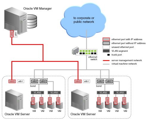
The VLAN Group needed to support the configuration shown in Figure 5.4, “Networks with VLANs and VLAN Group” contains two VLANs, with ID 2 and 3. The VLAN Group also contains two ports for each Oracle VM Server in the network. On each server, the ports are configured as a bond device. Once the VLAN Group is created, two virtual machine networks are added: the first network specifies the VLAN segment with ID 2 and the second network specifies the VLAN segment with ID 3, where both segments are defined in the VLAN Group. For each network, a bridge is defined for the specified VLAN segment, without an IP address since none is specified during configuration. Network packets from virtual machines deployed on VLAN segment 2 travel through the bridge and acquire a tag which identifies the packets as belonging to VLAN 2. Similarly, the packets issued from the virtual machines deployed on the network for VLAN segment 3 are tagged for VLAN3 with ID 3. The packets from both networks use either path to the switch if the bond is configured as active-active. The receiving ports on the Ethernet switch are configured using trunking or similar program to recognize network traffic for the two VLANs in the configuration. As such, the trunk ports will direct the packets to the correct VLAN on the switch, or other connected switches.