Improving Network and Server Efficiency by Using EVB
This section provides an example to show how you can increase server and network efficiency
when you enable EVB on a server.
This example assumes that the server hosts two applications in a cloud environment on the same
physical machine.
-
Applications are hosted on a cloud as separate virtual machines (VM1 and VM2) on a physical
machine. The VNICs VNIC1 and VNIC2 are configured for VM1 and
VM2 respectively.
-
Clients (Client 1 and Client 2) with an account can access the applications.
-
The virtual machines (VM1 and VM2) share the resources of the physical system and the
bandwidth on link L2.
-
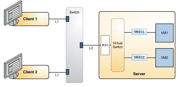
The clients are connected to the switch by using the link L1. The switch is connected to the
NIC by using the link L2.
-
Predetermined SLA determines the assignment of the resource for the virtual machines. The
following (L2) bandwidth usage is included for SLAs of the virtual machines:
-
VM1 is running a high priority Transmission Control Protocol (TCP) service. So, SLA for VM1
has the maximum bandwidth limit of 8 Gbps.
-
VM2 is running a User Datagram Protocol (UDP) service that is not high priority. So, SLA for
VM2 has the maximum bandwidth limit of 3 Gbps.
The following figure shows the applications hosted on a server.
Figure 4-1 Application Setup Without EVB

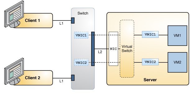
When you enable EVB on the server and the switch, the server exchanges the VNIC information
with the switch through the same physical switch port as shown in the following figure.
Figure 4-2 Application Setup With EVB Enabled

The following table shows the efficiency of the server before and after enabling EVB on the
server and switch.
Table 4-1 Efficiency of the Server Without EVB and With EVB
|
|
|
The server regulates incoming traffic from the clients for bandwidth enforcement.
|
The switch regulates the traffic destined to the server.
|
|
System resources are used, thereby affecting the system and network performance.
|
System resources are not used to process the bandwidth, thereby improving the system
efficiency.
|
In this example, when the clients (Client 1 and Client 2) need to utilize the services
simultaneously, the clients use the bandwidth of link L2 and server resources. The server enforces
the SLA on the VNICs for VM1 and VM2 to regulate the inbound and the outbound traffic of the
clients. However, network performance and bandwidth usage are affected in the following ways:
-
Traffic from the clients (Client 1 and Client 2) use the bandwidth of link L2 without any
restrictions. Also, if there is a bandwidth limit configured on the host, packets that use the
bandwidth of L2 might be dropped on the host, which results in inefficient use of the
bandwidth.
-
VM1 provides a high priority TCP service and VM2 provides UDP service that is not high
priority. Regulating VM1's bandwidth on the server causes TCP to respond, hence impacting VM1's use
of bandwidth on the link L2. However, regulating VM2's service on the server does not impact its
usage of the bandwidth of link L2. This affects other services using the link L2.
|
When EVB is enabled on the server and the switch, system efficiency increases in the following
ways:
-
SLA configured on the VNICs of the server are reflected on the switch.
-
Switch regulates the traffic towards VM1 and VM2 based on the configured bandwidth and
therefore helps to utilize the bandwidth of link L2 appropriately, thereby providing network
efficiency.
Because the switch regulates the bandwidth, the server does not have to process bandwidth on
the receive side, thereby providing server efficiency.
|
|
In this example, the network traffic for UDP and TCP services inbound to the server uses the
available bandwidth on the link L2 without any restrictions. After the server receives network
traffic, it regulates the network traffic based on the configured bandwidth limit.
|
The configured bandwidth limits (3 Gbps and 8 Gbps) are regulated by the switch in addition to
the server. Hence, the shared link L2's usage is based on the configured bandwidth limits.
|
|

