| Skip Navigation Links | |
| Exit Print View | |

|
Oracle VM Server for SPARC 3.0 Administration Guide Oracle VM Server for SPARC |
| Skip Navigation Links | |
| Exit Print View | |

|
Oracle VM Server for SPARC 3.0 Administration Guide Oracle VM Server for SPARC |
Part I Oracle VM Server for SPARC 3.0 Software
1. Overview of the Oracle VM Server for SPARC Software
2. Installing and Enabling Software
3. Oracle VM Server for SPARC Security
4. Setting Up Services and the Control Domain
Introduction to a Virtual Network
Oracle Solaris 10 Networking Overview
Oracle Solaris 11 Networking Overview
Virtual Device Identifier and Network Interface Name
How to Find Oracle Solaris OS Network Interface Name
Assigning MAC Addresses Automatically or Manually
Range of MAC Addresses Assigned to Logical Domains
Automatic Assignment Algorithm
Duplicate MAC Address Detection
Using Network Adapters With Logical Domains
How to Determine If a Network Adapter Is GLDv3-Compliant (Oracle Solaris 10)
Configuring a Virtual Switch and the Service Domain for NAT and Routing
Configuring NAT on an Oracle Solaris 10 System
How to Set Up a Virtual Switch to Provide External Connectivity to Domains (Oracle Solaris 10)
Configuring NAT on an Oracle Solaris 11 System
How to Set Up a Virtual Switch to Provide External Connectivity to Domains (Oracle Solaris 11)
Configuring IPMP in a Logical Domains Environment
Configuring Virtual Network Devices Into an IPMP Group in a Domain
Configuring and Using IPMP in the Service Domain
Using Link-Based IPMP in Logical Domains Virtual Networking
How to Configure Physical Link Status Updates
Configuring and Using IPMP in Releases Prior to Logical Domains 1.3
How to Assign VLANs to a Virtual Switch and Virtual Network Device
How to Install a Guest Domain When the Install Server Is in a VLAN
How to Configure a Virtual Switch With an NIU Network Device
Using Link Aggregation With a Virtual Switch
How to Configure Virtual Network and Virtual Switch Devices to Use Jumbo Frames
Compatibility With Older (Jumbo-Unaware) Versions of the vnet and vsw Drivers (Oracle Solaris 10)
Oracle Solaris 11 Networking-Specific Feature Differences
11. Managing Domain Configurations
12. Performing Other Administration Tasks
Part II Optional Oracle VM Server for SPARC Software
13. Oracle VM Server for SPARC Physical-to-Virtual Conversion Tool
14. Oracle VM Server for SPARC Configuration Assistant (Oracle Solaris 10)
16. Using the Oracle VM Server for SPARC Management Information Base Software
17. Logical Domains Manager Discovery
18. Using the XML Interface With the Logical Domains Manager
The Oracle VM Server for SPARC software supports link-based IP network multipathing (IPMP) with virtual network devices. When configuring an IPMP group with virtual network devices, configure the group to use link-based detection. If using older versions of the Oracle VM Server for SPARC (Logical Domains) software, you can only configure probe-based detection with virtual network devices.
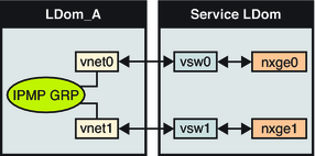
The following diagram shows two virtual networks (vnet0 and vnet1) connected to separate virtual switch instances (vsw0 and vsw1) in the service domain, which, in turn, use two different physical interfaces. The physical interfaces are nxge0 and nxge1 in Oracle Solaris 10 and net0 and net1 in Oracle Solaris 11. The diagram shows the Oracle Solaris 10 physical interface names. If a physical link failure occurs in the service domain, the virtual switch device that is bound to that physical device detects the link failure. Then, the virtual switch device propagates the failure to the corresponding virtual network device that is bound to this virtual switch. The virtual network device sends notification of this link event to the IP layer in the guest LDom_A, which results in failover to the other virtual network device in the IPMP group.
Figure 8-7 Two Virtual Networks Connected to Separate Virtual Switch Instances

Note - Figure 8-7 shows the configuration on an Oracle Solaris 10 system. For an Oracle Solaris 11 system, only the interface names change to use the generic names, such as net0 and net1 for nxge0 and nxge1, respectively.
Further reliability can be achieved in the logical domain by connecting each virtual network device (vnet0 and vnet1) to virtual switch instances in different service domains (as shown in the following diagram). In this case, in addition to physical network failure, LDom_A can detect virtual network failure and trigger a failover following a service domain crash or shutdown.
Figure 8-8 Each Virtual Network Device Connected to Different Service Domains

Note - Figure 8-8 shows the configuration on an Oracle Solaris 10 system. For an Oracle Solaris 11 system, only the interface names change to use the generic names, such as net0 and net1 for nxge0 and nxge1, respectively.
For more information, see the Oracle Solaris 10 System Administration Guide: IP Services or “Establishing an Oracle Solaris Network” in the Oracle Solaris 11.1 Information Library.
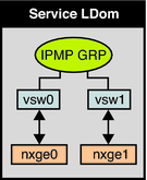
IPMP can be configured in the service domain by configuring virtual switch interfaces into a group. The following diagram shows two virtual switch instances (vsw0 and vsw1) that are bound to two different physical devices. The two virtual switch interfaces can then be created and configured into an IPMP group. In the event of a physical link failure, the virtual switch device that is bound to that physical device detects the link failure. Then, the virtual switch device sends notification of this link event to the IP layer in the service domain, which results in a failover to the other virtual switch device in the IPMP group. The two physical interfaces are nxge0 and nxge1 in Oracle Solaris 10 and net0 and net1 in Oracle Solaris 11. The following diagram shows the Oracle Solaris 10 physical interface names.
Figure 8-9 Two Virtual Switch Interfaces Configured as Part of an IPMP Group

Note - Figure 8-9 shows the configuration on an Oracle Solaris 10 system. For an Oracle Solaris 11 system, only the interface names change to use the generic names, such as net0 and net1 for nxge0 and nxge1, respectively.
The virtual network and virtual switch devices support link status updates to the network stack. By default, a virtual network device reports the status of its virtual link (its LDC to the virtual switch). This configuration is enabled by default and does not require you to perform additional configuration steps.
Sometimes it might be necessary to detect physical network link state changes. For instance, if a physical device has been assigned to a virtual switch, even if the link from a virtual network device to its virtual switch device is up, the physical network link from the service domain to the external network might be down. In such a case, it might be necessary to obtain and report the physical link status to the virtual network device and its stack.
The linkprop=phys-state option can be used to configure physical link state tracking for virtual network devices as well as for virtual switch devices. When this option is enabled, the virtual device (virtual network or virtual switch) reports its link state based on the physical link state while it is created as an interface in the domain. You can use standard Oracle Solaris network administration commands such as dladm and ifconfig to check the link status. In addition, the link status is also logged in the /var/adm/messages file.
For Oracle Solaris 10, see the dladm(1M) and ifconfig(1M) man pages. For Oracle Solaris 11, see the dladm(1M), ipadm(1M), and ipmpstat(1M) man pages.
Note - You can run both link-state-unaware and link-state-aware vnet and vsw drivers concurrently on a Logical Domains system. However, if you intend to configure link-based IPMP, you must install the link-state-aware driver. If you intend to enable physical link state updates, upgrade both the vnet and vsw drivers to the Oracle Solaris 10 8/11 OS, and run at least Version 1.3 of the Logical Domains Manager.
This procedure shows how to enable physical link status updates for virtual network devices.
You can also enable physical link status updates for a virtual switch device by following similar steps and specifying the linkprop=phys-state option to the ldm add-vsw and ldm set-vsw commands.
Note - You need to use the linkprop=phys-state option only if the virtual switch device itself is created as an interface. If linkprop=phys-state is specified and the physical link is down, the virtual network device reports its link status as down, even if the connection to the virtual switch is up. This situation occurs because the Oracle Solaris OS does not currently provide interfaces to report two distinct link states, such as virtual-link-state and physical-link-state.
For Oracle Solaris 10, see Configuring RBAC (Task Map) in System Administration Guide: Security Services. For Oracle Solaris 11.1, see Part III, Roles, Rights Profiles, and Privileges, in Oracle Solaris 11.1 Administration: Security Services.
You can enable physical link status updates for a virtual network device in the following ways:
Create a virtual network device by specifying linkprop=phys-state when running the ldm add-vnet command.
Specifying the linkprop=phys-state option configures the virtual network device to obtain physical link state updates and report them to the stack.
Note - If linkprop=phys-state is specified and the physical link is down (even if the connection to the virtual switch is up), the virtual network device reports its link status as down. This situation occurs because the Oracle Solaris OS does not currently provide interfaces to report two distinct link states, such as virtual-link-state and physical-link-state.
# ldm add-vnet linkprop=phys-state if-name vswitch-name ldom
The following example enables physical link status updates for vnet0 connected to primary-vsw0 on the logical domain ldom1:
# ldm add-vnet linkprop=phys-state vnet0 primary-vsw0 ldom1
Modify an existing virtual network device by specifying linkprop=phys-state when running the ldm set-vnet command.
# ldm set-vnet linkprop=phys-state if-name ldom
The following example enables physical link status updates for vnet0 on the logical domain ldom1:
# ldm set-vnet linkprop=phys-state vnet0 ldom1
To disable physical link state updates, specify linkprop= by running the ldm set-vnet command.
The following example disables physical link status updates for vnet0 on the logical domain ldom1:
# ldm set-vnet linkprop= vnet0 ldom1
Example 8-1 Configuring Link-Based IPMP
The following examples show how to configure link-based IPMP, both with and without enabling physical link status updates:
The following example configures two virtual network devices on a domain. Each virtual network device is connected to a separate virtual switch device on the service domain to use link-based IPMP.
Note - Test addresses are not configured on these virtual network devices. Also, you do not need to perform additional configuration when you use the ldm add-vnet command to create these virtual network devices.
The following commands add the virtual network devices to the domain. Note that because linkprop=phys-state is not specified, only the link to the virtual switch is monitored for state changes.
# ldm add-vnet vnet0 primary-vsw0 ldom1
# ldm add-vnet vnet1 primary-vsw1 ldom1
The following commands configure the virtual network devices on the guest domain and assign them to an IPMP group. Note that test addresses are not configured on these virtual network devices because link-based failure detection is being used.
Oracle Solaris 10 OS. Use the ifconfig command.
# ifconfig vnet0 plumb
# ifconfig vnet1 plumb
# ifconfig vnet0 192.168.1.1/24 up
# ifconfig vnet1 192.168.1.2/24 up
# ifconfig vnet0 group ipmp0
# ifconfig vnet1 group ipmp0
Oracle Solaris 11 OS. Use the ipadm command.
Note that net0 and net1 are the Oracle Solaris 11 vanity names for vnet0 and vnet1, respectively.
# ipadm create-ip net0
# ipadm create-ip net1
# ipadm create-ipmp ipmp0
# ipadm add-ipmp -i net0 -i net1 ipmp0
# ipadm create-addr -T static -a 192.168.1.1/24 ipmp0/v4addr1
# ipadm create-addr -T static -a 192.168.1.2/24 ipmp0/v4addr2
The following example configures two virtual network devices on a domain. Each domain is connected to a separate virtual switch device on the service domain to use link-based IPMP. The virtual network devices are also configured to obtain physical link state updates.
Note that net0 and net1 are the Oracle Solaris 11 vanity names for vnet0 and vnet1, respectively.
Oracle Solaris 10 OS. Use the following commands:
# ldm add-vnet linkprop=phys-state vnet0 primary-vsw0 ldom1
# ldm add-vnet linkprop=phys-state vnet1 primary-vsw1 ldom1
Oracle Solaris 11 OS. Use the following commands:
# ldm add-vnet linkprop=phys-state net0 primary-vsw0 ldom1
# ldm add-vnet linkprop=phys-state net1 primary-vsw1 ldom1
Note - The virtual switch must have a physical network device assigned for the domain to successfully bind. If the domain is already bound and the virtual switch does not have a physical network device assigned, the ldm add-vnet commands will fail.
The following commands create the virtual network devices and assign them to an IPMP group:
Oracle Solaris 10 OS. Use the ifconfig command.
# ifconfig vnet0 plumb
# ifconfig vnet1 plumb
# ifconfig vnet0 192.168.1.1/24 up
# ifconfig vnet1 192.168.1.2/24 up
# ifconfig vnet0 group ipmp0
# ifconfig vnet1 group ipmp0
Oracle Solaris 11 OS. Use the ipadm command.
Note that net0 and net1 are the vanity names for vnet0 and vnet1, respectively.
# ipadm create-ip net0
# ipadm create-ip net1
# ipadm create-ipmp ipmp0
# ipadm add-ipmp -i net0 -i net1 ipmp0
# ipadm create-addr -T static -a 192.168.1.1/24 ipmp0/v4addr1
# ipadm create-addr -T static -a 192.168.1.2/24 ipmp0/v4addr2
In Logical Domains releases prior to 1.3, the virtual switch and the virtual network devices are not capable of performing link failure detection. In those releases, network failure detection and recovery can be set up by using probe-based IPMP.
The virtual network devices in a guest domain can be configured into an IPMP group as shown in Figure 8-7 and Figure 8-8. The only difference is that probe-based failure detection is used by configuring test addresses on the virtual network devices. See System Administration Guide: IP Services for more information about configuring probe-based IPMP.
In Logical Domains releases prior to 1.3, the virtual switch device is not capable of physical link failure detection. In such cases, network failure detection and recovery can be set up by configuring the physical interfaces in the service domain into an IPMP group. To do this, configure the virtual switch in the service domain without assigning a physical network device to it. Namely, do not specify a value for the net-dev (net-dev=) property while you use the ldm add-vswitch command to create the virtual switch. Create the virtual switch interface in the service domain and configure the service domain itself to act as an IP router. Refer to the Oracle Solaris 10 System Administration Guide: IP Services for information about setting up IP routing.
Once configured, the virtual switch sends all packets originating from virtual networks (and destined for an external machine) to its IP layer, instead of sending the packets directly by means of the physical device. In the event of a physical interface failure, the IP layer detects failure and automatically re-routes packets through the secondary interface.
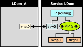
Since the physical interfaces are directly being configured into an IPMP group, the group can be set up for either link-based or probe-based detection. The following diagram shows two network interfaces (nxge0 and nxge1) configured as part of an IPMP group. The virtual switch instance (vsw0) has been created as a network device to send packets to its IP layer.
Figure 8-10 Two Network Interfaces Configured as Part of an IPMP Group

Note - Figure 8-10 shows the configuration on an Oracle Solaris 10 system. For an Oracle Solaris 11 system, only the interface names change to use the generic names, such as net0 and net1 for nxge0 and nxge1, respectively.
Note - This procedure only applies to guest domains and to releases prior to 1.3, where only probe-based IPMP is supported.
If no explicit route is configured for a router in the network corresponding to the IPMP interfaces, then one or more explicit host routes to target systems need to be configured for the IPMP probe-based detection to work as expected. Otherwise, probe detection can fail to detect the network failures.
# route add -host destination-IP gateway-IP -static
For example:
# route add -host 192.168.102.1 192.168.102.1 -static
Refer to Configuring Target Systems in System Administration Guide: IP Services for more information.