23 Oracle Engineered Systems
The following information is included in this section:
23.1 Introduction to Oracle Engineered Systems
Traditionally, IT departments have been required to install and configure software that is hosted on hardware that was itself installed and configured separately. Oracle Engineered Systems relieve this burden from the IT department by providing a pre-defined combination of hardware and software. Oracle Engineered Systems is a complete set of integrated hardware and software that is designed to reach a predetermined level of capability, capacity, and scale. This relatively new concept of an integrated hardware and software solution, dedicated to provide a specific service, changes the way one must think about architecture in IT environments.
In addition to removing the burden of installation and configuration, Oracle Engineered Systems provide significant cost savings, this is one of the many advantages delivered by Oracle Engineered Systems. An even larger advantage is the optimization that pre-defined hardware and software enables. As the hardware and software are engineered together to form a complete system, there are multiple opportunities to improve the overall system performance. The unified and integrated monitoring and management of the Oracle Engineered Systems also provide cost savings through simplification of the overall environment. Thus, Oracle Engineered Systems allow datacenter services to be delivered more efficiently through modular or dedicated systems. This greatly simplifies the entire purchase, deploy, configure, monitor, and manage lifecycle of the provided services.
The whole impetus for cloud computing is to provide specific services such as Infrastructure as a Service (IaaS), Platform as a Service (PaaS), or Software as a Service (SaaS) as efficiently as possible; therefore, the increased efficiency delivered by Oracle Engineered Systems make them ideal candidates for the building blocks of a cloud computing environment.
In addition to creating a cloud computing environment, the building blocks address a variety of enterprise architecture requirements to provide a path for enterprise maturation alongside the move to cloud adoption. Each building block is selected as needed to meet specific maturation needs, and thus, ultimately it provides an increase in overall architectural flexibility. For example, an architect may choose to integrate an Exadata Storage Server and Oracle SuperCluster or Oracle VM Blade Cluster early on to begin the process of consolidation into a scalable architecture, and then expand the system later to meet future demand. Shifting the overall environment into a standardized architecture opens possibilities for future shift into cloud adoption or continuation down the traditional enterprise computing maturation continuum while providing for future scale.
The following are the different Oracle Engineered Systems that are supported by Oracle Enterprise Manager Ops Center.
Oracle SPARC SuperCluster T4-4
Oracle SPARC SuperCluster T4-4 includes a complete stack of hardware and software, computing, storage, and network, all engineered to work optimally together to provide a consolidated platform for running database, middleware, or third party applications. Oracle Enterprise Manager Ops Center is closely integrated with SPARC SuperCluster and provides hardware management, provisioning, and virtualization management.
Oracle SuperCluster T5-8 includes a complete stack of hardware and software, computing, storage, and network, all engineered to work optimally together to provide a consolidated platform for running database, middleware, or third party applications. Oracle Enterprise Manager Ops Center is closely integrated with Oracle SuperCluster T5-8 and provides hardware management, provisioning, and virtualization management.
Oracle SuperCluster M6-32 is a complete engineered system that is designed to run databases and applications on a single system. Ideal for consolidation and private cloud, Oracle SuperCluster M6-32 can run database, middleware, custom and third party applications. Oracle SuperCluster M6-32 is ideal for large scale database and application consolidation and also private cloud. You can run a variety of workloads including OLTP and data warehousing, complex applications, and mixed workloads for extreme performance. With big memory, Oracle SuperCluster M6-32 can run databases and applications in memory while providing the highest levels of availability and serviceability. Oracle SuperCluster M6-32 can scale vertically, allowing customers to flexibly add compute and storage resources to meet their demanding datacenter requirements.
23.2 Understanding User Roles
In Oracle Enterprise Manager Ops Center, users are assigned several roles such as Asset Admin, Cloud Admin, SuperCluster Systems Admin, and many more. Each role grants the user a set of permissions; a particular permission can be granted by more than one role such as Asset Management, Network Management, and other management roles.
You can add users to Oracle Enterprise Manager Ops Center from the local authentication subsystem of the Enterprise Controller's operating system. Each user is given a different role which grants or denies access to the different functions of Oracle Enterprise Manager Ops Center.
The following user roles are described in this section:
23.2.1 Ops Center Administrator Role
The Ops Center Administrator user role is only used for initial discovery of the Oracle SuperCluster system. As an OpsCenter Admin user, though you have permissions, do not perform actions that are disabled for the SuperCluster Systems Admin Role. All discovery operations on Oracle SuperCluster systems must be started using OpsCenter Administrator account only.
When using Oracle Engineered Systems in Oracle Enterprise Manager Ops Center, some actions might be potentially dangerous; hence those actions are disabled.
See Asset Protection for more information.
23.2.2 SuperCluster Systems Admin Role
The SuperCluster Systems Administrator is responsible for overall monitoring and management of all associated Oracle SuperCluster systems. The SuperCluster Systems Administrator also has privileges to manage Virtual Pools, Storage, and Oracle Solaris Cluster. As a SuperCluster Systems Administrator, you can perform most of the operations that are allowed in the context of the Oracle SuperCluster system.
The SuperCluster Systems Administrator role is a default role recommended for the management of the Oracle SuperCluster system.
Prerequisites: The user must be familiar with the use of Oracle Enterprise Manager Ops Center and be familiar with hardware management and OS management in general.
23.2.2.1 Creating a SuperCluster Systems Administrator Role
You can create a SuperCluster Systems Administrator user to manage an Oracle SuperCluster system. You can create one or more users that have access to the same Oracle SuperCluster system.
Note:
Before you create a SuperCluster Systems Administrator role, create a user on your OS or connect to the LDAP sever.To create a SuperCluster Systems Administrator role, perform the following steps:
-
In the Navigation pane, click Administration.
-
Under Enterprise Controller, click Local Users.
-
In the Actions pane, click Add User.
-
In the User Name field, enter a name for the user role (for example, sscadmin, provided such local user exists on the OS or directory server if configured).
The sscadmin user requires a UNIX user on the Enterprise Controller system where Oracle Supercluster system will be managed and monitored. -
Select SuperCluster Systems Admin in the Available Roles section and click the right arrow to move the role to the Selected Roles section.
-
Click Add User. The new user role is added.
23.2.2.2 Assign Permissions to the Role
After you add the role, you must assign permissions to the new role that you created.
-
In the Navigation pane, click Administration.
-
Under Enterprise Controller, click Local Users.
-
In the center pane, click the Users tab.
-
Select the sscadmin user, then click the Manage User Roles icon.
-
In the User Roles screen, uncheck Use the default Role associations, then click Next.
-
In the Specify Asset Privileges screen, expand All Assets, then expand Oracle Engineered Systems.
-
Select the Oracle SuperCluster assets that you want the SuperCluster Systems Admin to manage.
-
Click Next on the following screens.
-
Review the Summary, then click Finish.
Only the Oracle SuperCluster assets that have been selected are displayed in the Navigation pane under All Assets.
Note:
The SuperCluster Systems Admin role prevents you from performing unsupported actions by mistake.23.2.2.3 SuperCluster Systems Admin Role Permissions
As a SuperCluster Systems Admin, you can perform most operations available in Oracle Enterprise Manager Ops Center. However, some operations are disabled because they could compromise pre-installed Oracle Engineered Systems' hardware or software infrastructure.
The following actions are disabled for SuperCluster Systems Admin user:
-
PDOM management (creating LDOMs on M-series servers)
-
LDOM management (Connect Network and Storage Management with the exception of Starting / Shutting down / Rebooting LDOM)
-
Install / Update OS on LDOMs and Global zones
-
Install Server
-
Rack management
-
Chassis management
-
Network Switch management
-
Network infrastructure operations (Attach network to global zone, IPMP operations)
-
Firmware updates
-
EC Management (downloads, upgrade, EC Proxy / Agent management, storage library management)
-
OVM management
-
Asset discovery
-
Create logical domain
-
Switch management (edit action is permitted)
-
Remove SuperCluster
Note:
Oracle Solaris cloud management operations and virtual datacenter (vDC) functionality cannot be performed by Supercluster Systems Admin user. To perform these actions, create Cloud Admin and Cloud User roles.23.2.3 Cloud Admin
The Cloud Administrator's responsibilities include setting up of infrastructure and resource allocation so that cloud users can deploy their application onto authorized accounts. They also manage the cloud users accessing the accounts and their authorization.
Prerequisites: The user must be trained on Oracle Enterprise Manager Ops Center, installation and configuration, and the continual maintenance of the product.
23.2.4 Cloud User
Cloud users create virtual servers and deploy applications. Cloud users are restricted to virtual datacenter infrastructure activities and are presented only with the required options on the Oracle Enterprise Manager Ops Center UI.
Prerequisites: The user must be familiar with the use of Oracle Enterprise Manager Ops Center, and also its hardware management and OS management in general.
23.3 Oracle Engineered Systems Management
This section describes in detail about Oracle Engineered Systems Management using which you can enable a single or centralized Oracle Enterprise Manager Ops Center installation managing multiple Oracle SuperCluster systems and other assets in the datacenter directly.
Using Oracle Enterprise Manager Ops Center, you can discover Engineered Systems from a single datacenter instance and perform complete management and monitoring of multiple engineered systems.
Figure 23-6 is a pictorial representation of datacenter management of engineered systems using Oracle Enterprise Manager Ops Center.
Figure 23-6 Oracle Engineered Systems Management
Description of "Figure 23-6 Oracle Engineered Systems Management"
23.3.1 Configuring Oracle Engineered Systems
This section describes the following scenarios:
23.3.1.1 Overlapping IB Networks Enabled
Overlapping IB networks are not supported by default, but starting with Oracle Enterprise Manager Ops Center 12c Release 2 (12.2.2.0.0), the same can be enabled. Overlapping network systems must be discovered only after the feature is enabled.
To enable overlapping IB networks, perform the following steps:
-
In the Navigation pane, under Administration, click Enterprise Controller.
-
In the center pane, click Configuration.
-
In the Configuration Management section, select Network/Fabric Manager from the Subsystem drop-down list.
-
Set the value of oem.oc.networkmgmt.ib.overlapping.enabled property file to true.
Note:
Restart the Enterprise Controller for the changes to take effect.23.3.1.2 Overlapping IB Networks not Enabled
One or more Oracle Engineered Systems can be discovered and managed by a single Oracle Enterprise Manager Ops Center instance based on the following conditions:
-
None of Oracle Engineered System instances have overlapping private networks connected through IPoIB, that is, networks that have the same CIDR (Classless Inter-Domain Routing) or networks that are sub-blocks of the same CIDR. For example, 192.0.2.1/21 and 192.0.2.1/24 are overlapping.
-
None of the Oracle Engineered System instances or generic datacenter assets have overlapping management or client access networks connected through Ethernet, that is, networks that have the same CIDR or networks that are sub-blocks of the same CIDR. For example, 192.0.2.1/21 and 192.0.2.1/24 are overlapping. As an exception, you can use the same CIDR (not sub-block) for multiple systems. For example, you can use 192.0.2.1/22 as a CIDR for Ethernet network on one or more engineered systems and/or generic datacenter assets.
-
None of the Oracle Engineered System instances have overlapping public networks connected through EoIB, that is, networks that have the same CIDR or networks that are sub-blocks of the same CIDR. For example, 192.0.2.1/21 and 192.0.2.1/24 are overlapping. As an exception, you can use the same CIDR (not sub-block) for multiple systems. For example, you can use 192.2.0.0/22 as a CIDR for public EoIB network on multiple engineered systems.
-
None of the networks configured in Oracle Enterprise Manager Ops Center overlaps with any network, that is, overlapping networks are not supported by Oracle Enterprise Manager Ops Center.
Note:
To manage two or more engineered systems that have overlapping networks or any networks already present in Oracle Enterprise Manager Ops Center, reconfigure one of the conflicting systems before it is discovered and managed by the same Oracle Enterprise Manager Ops Center.23.3.1.3 Limitations
Do not create server pools using private networks attached to members from two or more SuperCluster systems (racks). To create server pools with members from two or more SuperCluster systems, use public networks. Use private networks only in server pools with members belonging to the same SuperCluster system.
23.3.1.4 Example Oracle SuperCluster Network Configurations
The following are example Oracle SuperCluster network configurations that you can use when configuring the network to discover and manage Oracle SuperCluster systems. Status OK indicates a valid configuration and status Fail indicates an invalid configuration.
Table 23-1 Example SuperCluster Network Configuration-1
| 1 GbE | 10 GbE | IB | |
|---|---|---|---|
|
SuperCluster1 |
192.0.251.0/21 |
192.4.251.0/24 |
192.168.30.0/24 |
|
SuperCluster2 |
192.0.251.0/21 |
192.4.251.0/24 |
192.168.31.0/24 |
|
Status |
OK |
OK |
OK |
Status:
OK - SuperCluster1-1GbE and SuperCluster2-1GbE share the same network.
OK - SuperCluster1-10GbE and SuperCluster2-10GbE share the same network.
OK - SuperCluster1-IB does not overlap with SuperCluster2-IB.
Table 23-2 Example SuperCluster Network Configuration-2
| 1 GbE | 10 GbE | IB | |
|---|---|---|---|
|
SuperCluster1 |
192.0.251.0/21 |
192.0.250.0/24 |
192.168.30.0/24 - IB fabric connected with SuperCluster2 |
|
SuperCluster2 |
192.6.0.0/21 |
192.0.250.0/24 |
192.168.30.0/24 - IB fabric connected with SuperCluster1 |
|
Status |
OK |
OK |
OK |
Status:
OK - SuperCluster1-1GbE and SuperCluster2-1GbE represent different non-overlapping networks.
OK - SuperCluster1-10GbE and SuperCluster2-10GbE share the same network.
OK - SuperCluster1-IB and SuperCluster2-IB represent the same network as they are interconnected.
Table 23-3 Example SuperCluster Network Configuration-3
| 1 GbE | 10 GbE | IB | |
|---|---|---|---|
|
SuperCluster1 |
192.0.2.1/21 |
192.0.251.0/21 |
192.168.30.0/24 |
|
SuperCluster2 |
192.0.0.128/25 |
192.0.7.0/24 |
192.168.30.0/24 |
|
Status |
FAIL |
OK |
FAIL |
Status:
FAIL - SuperCluster1-1GbE and SuperCluster2-1GbE define overlapping networks.
OK - SuperCluster1-10GbE and SuperCluster2-10GbE represent different non-overlapping networks.
FAIL - SuperCluster1-1GbE and SuperCluster2-10GbE define overlapping networks.
FAIL - SuperCluster1-IB and SuperCluster2-IB do not define unique private networks (racks are not interconnected).
23.3.1.5 Oracle Solaris 11 Software Library Setup
When you discover an Oracle SuperCluster system, default install agents work only if the Oracle Solaris 11 Software Update Library is correctly setup, because Oracle Solaris uses Oracle Solaris 11 Software Update Library.
If Oracle Enterprise Manager Ops Center was just installed, initialize the Oracle Solaris 11 Software Update Library before the discovery is started as it will fail to install agents. Ensure that the Oracle Solaris 11 Software Update Library contains the correct Oracle Solaris packages that your Enterprise Controller and Proxy Controllers use and also the SRUs that are used on the Oracle Engineered System.
To manage generic assets, you also need the correct Oracle Solaris packages for each generic Solaris 11 managed OS. Typically, you must create a full copy of the Oracle Solaris 11 support repository.
Starting with Oracle Enterprise Manager Ops Center 12c Release 2 (12.2.2.0.0), Oracle SuperCluster Solaris 11 OS uses the default HMP packages delivered with Oracle SuperCluster / QFSDP, instead of packages normally delivered by Ops Center installation.
It is recommended to install agents in all domains.
23.3.1.6 Deploy Proxy Controller
Deploy the Proxy Controller only if you do not have a suitable Proxy Controller in Oracle Enterprise Manager Ops Center that can discover Oracle Engineered Systems.
Perform the following steps to deploy the Proxy Controller on Oracle Enterprise Manager Ops Center.
-
In the Navigation pane, click Administration.
-
In the Actions pane, click Deploy Proxy.
-
Select Remote Proxies, then click Next.
-
Enter the Proxy Hostname/IP, SSH User, SSH Password, Privileged Role, and Privileged Password in the respective fields.
-
Click Next. The Remote Proxy Controller is deployed. This might take a few minutes.
-
Review the Summary, then click Finish.
The Remote Proxy Controller is deployed on Oracle Enterprise Manager Ops Center.
You can now perform discovery of the Oracle Engineered Systems.
23.3.1.7 Prepare Setup for Oracle Engineered Systems Discovery
The setup is based on the following options:
-
Network is identified by the Enterprise Controller
-
Network is not identified by the Enterprise Controller
Note:
Ensure you have a Proxy Controller deployed that can access the network. To deploy a Proxy Controller, see Deploy Proxy Controller.Network is Identified by the Enterprise Controller
If the Enterprise Controller host identifies the management network of the Oracle SuperCluster (CIDR must be the same), ensure that the network is assigned to the Proxy Controller. If it is not assigned, assign the network to the Proxy Controller.
To assign the network to the Proxy Controller, perform the following steps:
-
In the Navigation pane, select Administration.
-
Select a Proxy Controller.
-
In the Actions pane, click Associate Networks.
Network is not Identified by the Enterprise Controller
If the Enterprise Controller host does not identify the network (Oracle Engineered System management network must be routable from it), create a fabric definition and a network for the fabric.
-
In the Navigation pane, under Networks, select Fabrics from the drop-down list.
-
In the Actions pane, click Define Ethernet Fabric.
-
In the Fabric Name field enter a name for the fabric.
-
(Optional) Enter the description.
-
Click Next.
-
Enter the VLAN ID Ranges, then click Next.
-
Select the networks to be associated with the fabric, then click Next.
-
Review the Summary, the click Finish.
A new fabric is created.
After the fabric is created, you must create a network for the new fabric.
-
In the Navigation pane, under Networks, select Networks from the drop-down list.
-
In the Actions pane, click Define Network.
-
In the Network IP field, enter the IP address (in CIDR format) of the network that represents the management network of the Oracle Engineered System you want to manage.
-
Enter the Gateway IP address.
-
In the Network Name field, enter a name for the network.
-
Click Next.
-
Assign the newly created fabric to the Proxy Controller, then click Next.
The setup is now ready for Oracle Engineered System discovery.
23.3.1.8 Ports for Oracle SuperCluster
The proxy Controller for an Oracle SuperCluster engineered system does not have unique ports or protocols. The following table summarizes the set of ports and their protocols used by Oracle SuperCluster.
Table 23-4 Required Ports and Protocols for Oracle SuperCluster
| Communication Direction | Protocol and Port | Purpose |
|---|---|---|
|
Proxy Controller to Exadata's ILOM Service Processors |
SSH, TCP: Port 22 IPMI, TCP, UDP: Port 623 |
Proxy Controller discovers, manages, and monitors the service processor of Exadata. |
|
Proxy Controller to Exadata cells |
SSH, TCP: Port 22 |
Proxy Controller discovers, manages, and monitors the compute nodes. |
|
Proxy Controller to Oracle ZFS Storage Appliance |
SSH, TCP: Port 22 IPMI, TCP, UDP: Port 623 |
Proxy Controller discovers, manages, and monitors the service processor of the storage appliance. |
|
Proxy Controller to Oracle ZFS Storage Appliance |
SSH: Port 215 |
Proxy Controller discovers the projects of the storage appliance:
|
|
Proxy Controller to Cisco switch |
SSH version 2: Port 22 SNMP: Port 161 |
Proxy Controller discovers and manages the switch |
|
Proxy Controller to InfiniBand switch |
SSH: Port 22 IPMI: Port 623 |
Proxy Controller discovers and manages the switch. |
23.3.2 Discovering Oracle Engineered Systems
Oracle SuperCluster can be discovered only by trained Oracle staff. Oracle SuperCluster discovery is supported as a free service during Oracle SuperCluster installation only. You must request Oracle SuperCluster discovery before the Oracle SuperCluster installation.
Note:
After Oracle SuperCluster installation, Oracle SuperCluster discovery is offered only as a paid service.23.3.3 Asset Protection
Some actions in Oracle Enterprise Manager Ops Center might break an Oracle SuperCluster engineered system configuration. To protect the engineered system from inadvertent changes in the configuration and the resulting loss of service, high-risk actions are disabled for all users. For example, modifying logical domains or network configuration might break the engineered system configuration leading to loss of service.
The following actions are disabled for all users, including Ops Center Admin:
Control Domains
-
Attach Network
-
Create Logical Domains
-
Cancel Delayed Reconfiguration
Logical Domains
-
Delete logical domain
-
Migrate logical domain
-
Connect network
-
Add storage
-
Move metadata
-
Edit attributes of logical domain (with exception of name and description)
-
Enable/Disable automatic recovery
-
Network/Network Connectivity operations
-
Network/Link Aggregation operations
-
Network/IPMP group operations
-
Network/Bandwidth Flow operations
Global Zones
-
Network/Network Connectivity operations
-
Network/IPMP group operations
-
Network/Bandwidth Flow operations
Common Operations
-
Install Software
-
Deploy/Update Software
-
Update Firmware
-
Update BIOS
23.3.3.1 Disable Asset Protection
The Ops center Administrator role has special privilege to turn off the Asset protection feature in engineered systems.
Note:
Use this privilege for emergency purpose only.Enable the oes.asset.protection.override.user parameter in the /opt/sun/n1gc/lib/XVM_SATELLITE.properties file to allow all actions, including actions disabled by asset protection.
The Oracle Enterprise Manager OpsCenter Enterprise Controller must be restarted for changes in the XVM_SATELLITE.properties file to take effect.
23.3.4 Adding Multiple Racks
You can add multiple racks to a single Engineered System. To add multiple racks, you need different configuration files in respect to assets that you want to mount on the additional racks. After the configuration files are uploaded and validated, they are merged into a single profile, thus representing a single Engineered System.
Perform the following steps to add multiple racks to the Engineered System asset:
-
In the Navigation pane, click Plan Management.
-
Under Profiles and Policies, click Discovery, then click the discovery profile that you used to discover the Engineered System.
Figure 23-7 Select Engineered System Discovery Profile
Description of "Figure 23-7 Select Engineered System Discovery Profile"
-
In the Actions pane, click Edit Profile.
-
Click Next.
-
Click Next. The Configuration Files wizard is displayed.
-
Click Browse to select the configuration file for a new rack that you want to add to the Engineered System.
-
Click Upload to upload the configuration file.
You can also embed discovery information of multiple racks into a single configuration file. -
Click Next, then click Finish to create a discovery profile.
-
Run the discovery profile with the new configuration file. See Discovering Oracle Engineered Systems.
The additional rack is discovered and displayed under the respective Engineered System.
Figure 23-8 Multiple Racks Under a Single Engineered System
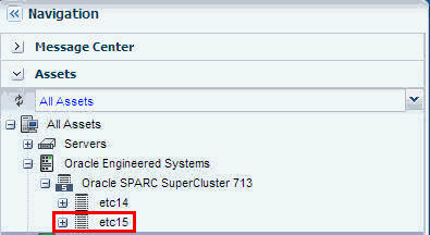
Description of "Figure 23-8 Multiple Racks Under a Single Engineered System"
23.3.5 Adding Oracle SuperCluster M6-32 Server
You can add additional Oracle SuperCluster M6-32 servers to the Oracle Engineered System using Oracle Enterprise Manager Ops Center.
Perform the following steps to add an Oracle SuperCluster M6-32 server to the Engineered System asset:
-
Create a discovery profile.
-
Upload the configuration file to discover the Oracle SuperCluster M6-32 server.
-
Click Finish to create the discovery profile.
Add the Oracle SuperCluster M6-32 Server
After the discovery profile is successfully created, run the discovery job and add the Oracle SuperCluster M6-32 server to the Oracle Engineered System asset.
Perform the following steps to add the Oracle SuperCluster M6-32 server:
-
In the Navigation pane, click All Assets.
-
In the Actions pane, click Add Assets.
-
Select Add and manage various types of assets via discovery probes, then click Next.
-
Select the discovery profile that you created to add the Oracle SuperCluster M6-32 server, then click Add Now.
The Oracle SuperCluster M6-32 server is discovered and displayed under Assets in the Navigation pane.Figure 23-9 Oracle SuperCluster M6-32 Server
Description of "Figure 23-9 Oracle SuperCluster M6-32 Server"
23.3.6 Adding Additional Hardware to the Rack
You can add additional hardware to the existing Engineered System rack. To add additional hardware, ensure you update the configuration file that was used originally for the discovery of the Oracle Engineered System asset with metadata information of the new hardware that you want to add.
Perform the following steps to add additional hardware:
-
In the Navigation pane, click Plan Management.
-
Under Profiles and Policies, click Discovery.
The discovery profiles are listed. -
Select the discovery profile for which you want to upload the updated configuration file.
-
Click the Edit Profile icon.
-
Click Next in the Identity Profile screen.
-
Click Next in the Tags screen.
-
In the Configuration Files(s) screen, click the Browse button to select the updated configuration file, then click Upload.
-
After the configuration file is uploaded successfully, click Next.
-
Review the Summary, then click Finish to create the discovery profile.
After the discovery profile is successfully created, run the discovery job and add the additional hardware to the same rack that is mounted on the Oracle Engineered System asset.
Perform the following steps to add the additional hardware to the Oracle Engineered System rack.
-
In the Navigation pane, click All Assets.
-
In the Actions pane, click Add Assets.
-
Select Add and manage various types of assets via discovery probes, then click Next.
-
Select the discovery profile that you updated to add the additional hardware, then click Add Now.
The additional hardware is discovered and displayed under All Assets in the Oracle Engineered Systems pool in the Navigation pane.
23.3.7 Viewing the Oracle Engineered Systems
You can view all types of engineered systems in the Navigation pane under All Assets. The engineered system assets are grouped by racks on which they are mounted. Assets mounted on a rack are grouped by gear type.
-
In the Navigation pane, under Assets, select All Assets.
-
Expand Oracle Engineered Systems.
The Engineered System assets are displayed.
In Figure 23-11, Engineered System assets (Oracle SPARC SuperCluster T4-4 and Oracle SuperCluster M6-32) are grouped by racks on which they are mounted.
The photorealistic view represents the physical rack where you can view the placement of the rack and its components. The front and rear views of the rack are displayed in this view. All slots and the respective assets are displayed.
Each asset in the rack is represented by an image. The health status of assets such as OK, Warning, or Critical is displayed in the form of colored lights as seen on the physical rack itself. OK status is identified by the green color. Warning and critical status are identified by the yellow color. Hover the mouse over the slots in the rack and view details about the assets such as slot number, asset name and description, type of asset, model number of the asset, and its health status.
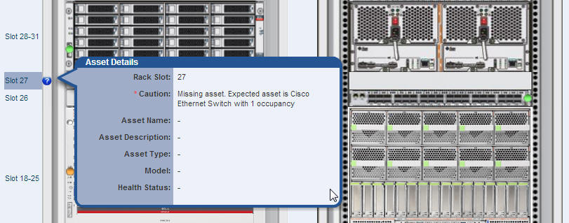
A question mark in any of the slots indicates a discrepancy from the baseline check. See Baseline Check for more information. For example, see Figure 23-12.
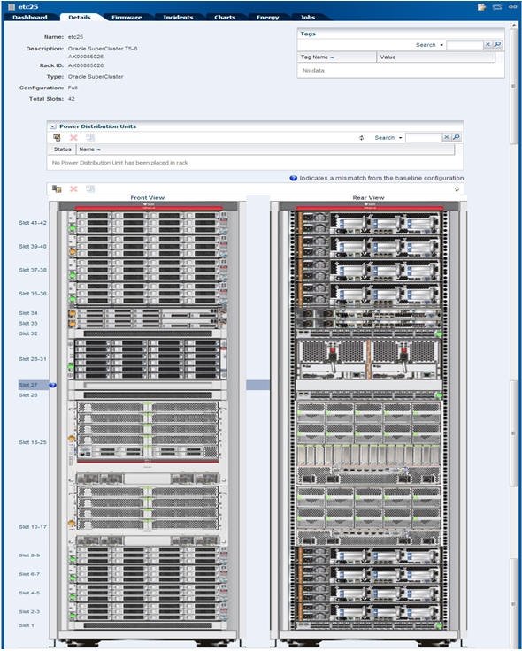
In this document, photorealistic view of the Oracle SuperCluster T5-8 rack is described.
To see the photorealistic view of the rack, perform the following steps:
-
In the Navigation pane, under Assets, select an asset from Oracle Engineered Systems.
-
Select a rack that you want to view.
-
In the center pane, click the Details tab.
A photorealistic view of the Oracle Engineered System rack is displayed.
Figure 23-13 Photorealistic view of Oracle SuperCluster System
Description of "Figure 23-13 Photorealistic view of Oracle SuperCluster System"
23.3.8 Creating Oracle Engineered Systems Report
Reports provide information about assets, such as job history, firmware, operating system updates, and incidents. Reports are created in Interactive, PDF, and CSV formats. You can generate and view the report for multiple Oracle Engineered Systems.
Perform the following steps to create a report for Oracle Engineered System.
-
In the Navigation pane, click Reports.
-
Click Oracle Engineered System Reports.
-
In the Actions pane, click Create Oracle Engineered System Report.
-
In the Define Report Parameters wizard, enter a name and description for the report.
The Schedule and Output Format are checked by default.-
Select Create Schedule to run the report later or on a recurring schedule.
-
Select the output formats of the result that will be generated for the report.
-
-
In the Targets section, select the asset for which you want to run the report and click Add to Target List.
-
Click Next. The Schedule wizard is displayed.
-
Select a schedule for the report. You can schedule the report to run on the following instances:
-
Now: Runs the report immediately.
-
At a later date/time: Select a date and time to generate the report.
-
On a Recurring Schedule: Select the month and day when you want to generate the report. Select the Start Time, End Time, and Number of Hours between runs. This is to set the number of times the report is generated between the specified start and end time. For example, if you set the start time at 6.00 a.m, end time at 12.00 a.m, and the number of hours between runs as 2, then the report is run at 6.00 a.m, 8.00 a.m, 10.00 a.m, and 12.00 a.m.
-
-
Click Next. The Summary wizard is displayed.
-
Verify the report parameters and click one of the options as required:
-
Save Template and Close: Saves the report as a template and closes the wizard. You can use the report template to generate the report later.
-
Run and Close: Runs the report and closes the wizard window.
-
View the Engineered System Report
Using reports, you can view the rack setup for each of the rack within the system, including the asset details related to the rack.
To view an Engineered System Report, perform the following steps.
-
In the Navigation pane, under Reports, select Oracle Engineered System Reports.
-
Select a report and click the format in which you want to view the report.
The report is displayed in the selected format.
23.4 Oracle SuperCluster
Oracle SuperCluster is an Oracle Engineered System that integrates SPARC compute nodes, a Sun ZFS Storage Appliance, InfiniBand switches, PDUs, and Exadata Storage Servers into a multi-rack system.
Oracle SuperCluster is supported in the following configurations:
-
Oracle SPARC SuperCluster T4-4: The Oracle SPARC SuperCluster T4-4 hardware includes two SPARC T4-4 servers, three Sun Datacenter InfiniBand Switch 36 switches as InfiniBand backplane, a Cisco 4948 48-port 1Gb Ethernet Switch for external connectivity (SSH version 2 only supported), and a Sun Rack II. Oracle SPARC SuperCluster T4-4 is available in two configurations, half rack and full rack. The half rack includes two SPARC T4-4 servers (with four processor modules per server) and three Exadata Storage Servers. The full rack includes four SPARC T4-4 servers (with four processor modules per server) and six Exadata Storage Servers. In addition, for additional storage capacity, connecting to an Oracle Exadata Storage Expansion Rack is supported.
-
Oracle SuperCluster T5-8: The Oracle SuperCluster T5-8 hardware includes two SPARC T5-8 servers, three Sun Datacenter InfiniBand Switch 36 switches as InfiniBand backplane, a Cisco 4948 48-port 1Gb Ethernet Switch for external connectivity (SSH version 2 only supported), and a Sun Rack II. Oracle SuperCluster T5-8 is available in two configurations, half rack and full rack. The half rack includes two SPARC T5-8 servers (with four processor modules per server) and four Exadata Storage Servers. The full rack includes two SPARC T5-8 servers (with eight processor modules per server) and eight Exadata Storage Servers. In addition, for additional storage capacity, connecting to an Oracle Exadata Storage Expansion Rack is supported.
-
Oracle SuperCluster M6-32: Oracle SuperCluster M6-32 delivers 16, 24, or 32 M6 processors with up to 32 TB of memory in a dedicated SPARC M6–32 rack. Compute capacity can be assigned flexibly, depending on customer requirements. Layered Optimized Virtualization allows resources to be configured hierarchically in physical domains (PDoms), logical domains (LDoms), and Oracle Solaris Zones. The SPARC M6-32 server delivers mainframe-class availability; two chassis may also be configured for extreme redundancy. An external storage rack provides nine Exadata Storage Servers, a ZFS Storage Appliance, three Sun Data center InfiniBand Switch 36 switches, and a Cisco 4948 48-port 1Gb Ethernet Switch (SSH version 2 only supported). Additional Oracle Exadata Storage Expansion Racks can be added as required.
Note:
Oracle Sun ZFS Storage 7320, Oracle Sun ZFS Storage 7420, and Oracle ZFS Storage ZS3-ES appliances provide a two-node cluster configuration. To discover the storage appliance, the administrative interfaces of both nodes must be private so that each node has a different static IP address. To verify that the appliance's nodes are using private administrative interfaces, you must use the appliance's user interface. For steps on how to determine if the interface is private, see Oracle ZFS Storage Appliance.23.4.1 Viewing the Oracle SuperCluster System
You can view the Oracle SuperCluster system virtually using the tabs on the center pane, namely Dashboard, Details, Networks, and Incidents. You can also perform actions by clicking the respective actions on the Actions pane. The actions available on the Actions pane depend on the selected asset in the Navigation pane. The actions are also role based, not all users are allowed to perform all actions. For more information on Roles, see Understanding User Roles.
Note:
In this document, it is assumed that Oracle SuperCluster is configured and discovered in Oracle Enterprise Manager Ops Center.To view the Oracle SuperCluster system, perform the following steps:
-
Log in to Oracle Enterprise Manager Ops Center using the Oracle SuperCluster Systems Admin role.
-
In the Navigation pane, under Assets, expand Oracle Engineered Systems.
Figure 23-18 Navigation to SuperCluster System
Description of "Figure 23-18 Navigation to SuperCluster System"
-
Select the Oracle SuperCluster system.
The Dashboard, Details, Networks, and Incidents tabs are displayed in the center pane.
Figure 23-19 SuperCluster System Center Pane
Description of "Figure 23-19 SuperCluster System Center Pane"
-
Click the required tab on the center pane to view more details.
-
Dashboard Tab displays the summary of the SuperCluster system, its membership graph, and the status of the system with details of all incidents.
-
Details Tab displays the name and description of the Oracle SuperCluster system. It also displays the number of racks, compute nodes, storage nodes, Exadata storage servers switches, PDUs, and fabrics present in the system.
-
Networks Tab displays the Infrastructure Networks table and Network Connectivity table.
-
Incidents Tab displays all the unresolved incidents and alerts reported in the Oracle SuperCluster system.
-
23.4.1.1 Dashboard Tab
The dashboard includes three sections namely, Summary, Membership Graph, and Status.
The Summary section displays the name of the Oracle SuperCluster system, description or the name of the system identifier, number of racks that are part of the system, and the number of unassigned incidents. The Unassigned Incidents icon in the summary pane includes incidents resulting from hardware faults. The three icons depict Critical Incidents, Warnings, and Information Incidents respectively.
The incidents are from all the assets that belong to a single Oracle SuperCluster Engineered System that includes multiple racks, or even systems with common IB backbone. If there are two systems, click each of them to display only incidents for assets that belong to that particular engineered system.
The Membership Graph pane displays the Oracle SuperCluster system as a hierarchy of its components showing the relationship between the Oracle SuperCluster system and fabrics that are grouped in the rack. You can instantly navigate to any asset by double-clicking on the asset in the membership graph.
Using the controls on the top right of the graphic pane, you can change the view of the graph to either a horizontal or a vertical orientation. You can also refresh the view by clicking the Refresh icon. You can also change the graph depths or size of the images.
The Status Pane displays the total unassigned incidents in chart format and also the recent incidents encountered by the Oracle SuperCluster system. In the Recent Incidents section, the following details are displayed:
-
Severity displays the severity of the incident.
-
State displays the state of the incident.
-
ID displays the incident ID.
-
Description displays the incident description.
-
Source displays the source of the incident.
-
Owner identifies the admin that is assigned to the incident and responsible for taking corrective action on the incident.
-
Creation Date displays the date on which the incident was created.
-
Current Status displays a current status icon of the incident, such as Critical / Warning / Info / Cleared.
23.4.1.2 Details Tab
In the Details Tab, the following details are displayed:
-
Name of the Oracle SuperCluster System
-
Description
-
Master Subnet Manager
-
Number of Racks
-
Number of Compute Nodes
-
Number of Storage Nodes
-
Number of Exadata Storage Servers
-
Number of Switches
-
Number of PDUs
-
Number of Fabrics
In the Tags pane, the tag names and their values are displayed. You can search for a particular tag using the Search feature.
23.4.1.3 Networks Tab
The Networks Tab displays the Infrastructure Networks Table and Network Connectivity Table.
The Infrastructure Networks Table displays the infrastructure networks that are defined and used inside the Oracle SuperCluster system for communication between the Oracle SuperCluster control components.
-
Network Name specifies the name of the managed network.
-
Network CIDR specifies the network.
-
Partition Key specifies the IB network partition key.
-
IP Range specifies the minimum and maximum boundaries of the IP addresses assigned to the network.
-
Roles specifies the role of the network.
The Network Connectivity Table displays the infrastructure networks with IPs assigned to the individual hardware components of the Oracle SuperCluster system.
-
Network Name
-
Asset Type
23.4.2 Viewing the Oracle SuperCluster System Rack
This section describes how to view the Oracle SuperCluster System rack, visualization of the rack physical layout, aggregated rack components, energy data, and other rack details. As an administrator, you can drill down to an asset contained in the rack (server, storage node, switch, Exadata Cells) or even further.
To view the Oracle SuperCluster System rack, perform the following steps:
-
In the Navigation pane, under Assets, expand Oracle Engineered Systems.
Figure 23-20 Navigation to SuperCluster System Rack
Description of "Figure 23-20 Navigation to SuperCluster System Rack"
-
Select a SuperCluster system, then select the rack that you want to view.
The Dashboard, Details, Firmware, Incidents, Charts, Energy, and Jobs tabs are displayed in the center pane.
Figure 23-21 SuperCluster System Rack Center Pane
Description of "Figure 23-21 SuperCluster System Rack Center Pane"
-
Dashboard Tab displays the summary, membership graph, and status of the rack.
-
Details Tab displays the rack info with a photorealistic view of the rack.
-
Firmware Tab displays details of the Compute Nodes, Switches, Storage Appliances, Exadata Storage Servers, and Power Distribution Units in the SuperCluster system
-
Incidents Tab displays the unresolved incidents and alerts for the selected SuperCluster system.
-
Charts Tab displays the chart of the aggregate power usage of the selected SuperCluster system. It provides more ways to display the power utilization data. You can change the graphed data to a bar chart or an area chart. You can also export the data for either the current view or all available data to a file in either CSV or XML format.
-
Energy Tab reports details of the Energy Performance such as Aggregate Power Consumption, Top and Bottom Consumers of Power and CPU Resources, and Average Power Consumption and CPU Utilization of the selected SuperCluster system rack.
-
Jobs Tab displays the current and historical jobs.
-
-
Click any of the tabs to view more details of the rack.
23.4.3 Viewing the Exadata Storage Server
The Exadata Storage Server provides storage for the Oracle SuperCluster system. It is a sub-type of the Linux server installed to be a database node.The Exadata Storage Servers are grouped together in the Navigation pane. In the same way that you view the Oracle SuperCluster system and its rack, you can also view the Exadata Storage Servers.
To view the Exadata Storage Server, perform the following:
-
In the Navigation pane, under Assets, expand Oracle Engineered Systems.
-
Select the Oracle SuperCluster asset.
-
Expand Exadata Storage Servers, and select an Exadata Storage Server. The server details are displayed on the center pane. Select the respective tabs on the center pane to view or perform actions.
Figure 23-22 View of Exadata Storage Servers
Description of "Figure 23-22 View of Exadata Storage Servers"
Refer To
Hardware Monitoringsection in the Hardware Management Guide for information on the different views and tasks that can be performed on the server cells.
23.4.4 Discovering an Oracle SuperCluster Component
Manual discovery is necessary if a component has been replaced or some properties of a component has changed autonomously. The component can either be a compute node, storage, or switch.
To manually discover an Oracle SuperCluster component, perform the following:
-
In the Navigation pane, select Plan Management.
-
Select Profiles and Policies, then select Discovery.
The available discovery profiles are listed in the center pane.
-
Select the required stored discovery profile and edit the profile and metadata if required.
-
Click Finish. The profile is updated.
Run the discovery using the updated profile to discover the Oracle SuperCluster component. See Discovering Oracle Engineered Systems.
23.5 Embedded Engineered Systems Management
Using Oracle Enterprise Manager Ops Center, you can discover and manage Oracle Engineered Systems. You can view and access multiple Engineered Systems from a single datacenter through Oracle Enterprise Manager Ops Center. You can also view the Engineered System's assets, incidents reported from the Engineered Systems, and Service Requests from the same UI. You can generate reports for all datacenter assets, including Engineered Systems.
The discovery and management process is performed using one of the following methods:
23.5.1 Finding Assets
The Find Assets action is disabled by default. Refer Service Tag Discovery for more information.
You can find assets using their service tags. Service tags are XML files containing product information. Many Oracle systems come equipped with service tags. You can discover hardware assets equipped with service tags using the Find Assets Wizard. This method lets you discover large number of assets quickly.
The Find Assets Wizard searches IP ranges or networks for service tags, then uses credentials that you specify to discover and manage the discovered assets.
Note:
Products without service tags cannot be discovered using this method. By default, service tags are enabled only on Oracle Exalogic Elastic Cloud Engineered Systems.To find assets, perform the following steps:
-
In the Navigation pane, under Assets, select All Assets.
-
In the Actions pane, click Find Assets. The Find Assets Wizard opens.
-
Select Find Assets Now and click Next.
When the initial discovery is complete, select the assets in each category (hardware, operating systems, and engineered systems) that you want to manage and provide necessary credentials.
Note:
When adding a network range, enter the values without any space between the IP addresses. Use the format start_ip-end_ ip. -
Click Finish. The manage asset job is launched.
See Discovering and Managing Assets for more information.
23.5.2 Adding Embedded Engineered System Assets
Embedded Oracle Engineered Systems is managed by a dedicated Oracle Enterprise Manager Ops Center running inside the engineered system fabric. You can add and manage a single or multiple Embedded Engineered System assets using Oracle Enterprise Manager Ops Center. To discover or add an asset, create a discovery profile. After you create the discovery profile, you can use the discovery profile to add the assets.
23.5.2.1 Creating a Discovery Profile
To create a discovery profile, perform the following steps:
-
In the Navigation pane, select Plan Management.
-
Under Profiles and Policies, select Discovery.
-
In the Actions pane, click Create Profile.
-
Enter a Name and Description for the discovery profile (description is optional).
-
In the Asset Type, expand Oracle Engineered Systems, then select Embedded Oracle Engineered System.
-
Click Next.
-
Enter Tags as necessary, then click Next.
-
(Optional) Enter the IP range. To use the existing IP range, select it.
-
Host names or IPs: Enter a comma-separated list of host names or IP addresses. To target an IP range, use the IP Ranges field instead.
-
Network: The managed network associated with the host names or IP addresses to route the discovery to the correct Proxy Controller. Select Automatic to route the job to the most appropriate Proxy Controller. The IP address of a target must resolve to only one known network for automatic routing to succeed.
-
IP Ranges: Click the plus icon to add one or more IP ranges. Enter a name, description (optional), network, and IP range for each. To target specific host names or IP addresses, you must enter them when you run the discovery profile.
-
-
Enter credentials for the JMX protocol.
The Java Management Extension (JMX) protocol is exclusively used to discover engineered system assets.
-
Review the summary and click Finish to create the discovery profile.
Refer Asset Management for additional information on discovering and adding assets in Oracle Enterprise Manager Ops Center.
23.5.2.2 Adding Assets Using a Discovery Profile
After you have created a discovery profile, you run a discovery job and manage Engineered System's assets. This lets you discover assets using a pre-existing set of protocols and credentials, and manage assets consistently.
To declare unconfigured assets for service processor configuration, perform the following steps:
-
In the Navigation pane, under Assets, select All Assets.
-
In the Actions pane, click Add Assets. The Add Assets Wizard opens.
-
Select the option, Add and manage various types of assets via discovery probes. The Discovery profile window opens.
-
Select a discovery profile that you created for discovering the embedded engineered system asset.
-
Add or edit the IP addresses, host names, and credentials for the targets.
-
Click Add Now. The Add Assets job is run. This might take a few minutes.
23.5.3 Viewing the Embedded Engineered Systems
You can view the Embedded Engineered System assets in the Datacenter Enterprise Controller BUI.
To view the Engineered System assets in the Datacenter Enterprise Controller BUI, perform the following steps:
-
In the Navigation pane, under Assets, expand Embedded Oracle Engineered Systems.
-
Select the Engineered System that you want to view. The Dashboard, Details, Rack Info, Incidents, Service Request, and Monitoring tabs are displayed in the center pane.
-
Dashboard Tab: Displays the summary of the selected Engineered System, its membership graph, and the status of the system.
-
Details Tab: Displays the name of the selected Engineered System, description, master subnet manager address, number of racks, compute nodes, storage nodes, switches, and PDUs in the system.
-
Rack Info Tab: Displays a photorealistic view of the selected Engineered System.
-
Incidents Tab: Displays all incidents reported from the selected Engineered System.
-
Service Request Tab: Displays the service request for the selected Engineered System.
-
Monitoring Tab: Displays the alert monitoring rules and service dependencies of the selected Engineered System.
-
To perform active management actions on any Oracle Engineered System asset, click Launch Web Interface in the Actions pane to launch the web interface of the selected Oracle Engineered System.
23.5.4 Viewing Relayed Incidents
Relayed Incidents are datacenter incidents that are reported from Oracle Engineered Systems attached to Datacenter Enterprise Controller. You can only view and delete the relayed incidents. No actions can be performed on these incidents.
When you close the relayed incidents from the Datacenter Enterprise Controller, the incidents are closed in the respective Engineered System as well.
To view all datacenter incidents, perform the following:
In the Navigation pane, under Message Center, select Relayed Incidents.
All the relayed incidents are displayed.
See Incidents for more information.
23.5.5 Viewing Relayed Service Requests
You can view the relayed service requests related to the Oracle Engineered Systems. You can also file service requests.
To view the relayed service requests, perform the following:
In the Navigation pane, under Message Center, select Relayed Service Requests.
All the relayed service requests are displayed. Details such as summary of the request, SR number, serial number, severity, status, contact person, and last updated date are displayed.
See Oracle Services and Service Requests for more information.
23.5.6 Baseline Check
Baseline Check is a feature in Oracle Enterprise Manager Ops Center Engineered Systems where the factory default configuration of eighth, quarter, half, and full rack configurations are considered as a normal or baseline setup. When the assets are discovered and associated with the rack, this setup is compared with the default factory configuration. If any discrepancy is found, the baseline check displays a question mark on the slot in the rack where the local configuration differs from the factory default configuration.
Hover the cursor over the question mark to view details of the warning, for example, missing asset, asset mismatch, or unknown asset. Based on the warning, you can decide to adjust and move the assets in the rack.
23.6 Related Resources for Engineered Systems
For instructions on performing general Oracle Enterprise Manager Ops Center actions, see the following resources.
-
See the Deploy How To library at http://docs.oracle.com/cd/E40871_01/nav/deployhowto.htm.
-
See the Operate How To library at http://docs.oracle.com/cd/E40871_01/nav/operatehowto.htm.