This section describes the preparation steps to perform before installing an additional compute node as part of your Oracle Virtual Compute Appliance.
When adding expansion nodes, always populate the compute rack units starting from the bottom most open slot, and work your way up. If you do not populate the rack units in the right order, the monitoring software may no longer report the correct status of the rack components.
Perform the following procedure to unpack the server upgrade kit.
Remove the packaging from the Oracle Virtual Compute Appliance Expansion Node upgrade kit.
Verify that all items are included. The upgrade kit should contain the following:
Sun Server X4-2
Cable management arm assembly with installation instructions
Rack-mount kit containing rack rails and installation instructions
(Optional) Sun server documentation
NoteCables are not included in the server upgrade kit. Oracle Virtual Compute Appliance comes with pre-installed and labeled cables for all rack units. These should not be unplugged or removed from the rack.
Perform the following procedure to prepare the rack.
To reduce the risk of personal injury, stabilize the rack cabinet and extend all anti-tilt devices before performing this procedure.
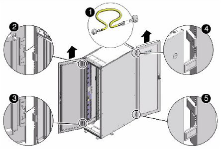
Remove the Oracle Virtual Compute Appliance front and rear rack doors, as follows:
Unlock the front and rear rack doors.
Open the doors.
Detach the grounding straps connected to the doors by pressing down on the tabs of the grounding strap's quick-release connectors, and pull the straps from the frame.
Lift the doors up and off their hinges. See Figure 6.1.
Table 6.2 Figure Legend
Item
Description
1
Detaching the grounding cable
2
Top rear hinge
3
Bottom rear hinge
4
Top front hinge
5
Bottom front hinge
Remove the filler panel(s) where the upgrade server will be installed.
The filler panels have snap-in attachments. No screwdriver is required to remove them.
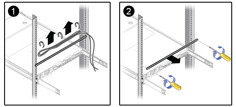
Remove the lacer bar that holds the pre-installed cables in place at the rear side of the rack. See Figure 6.2
Detach the pre-installed cables from the lacer bar on the rack unit for the new expansion node.
Use a No. 2 Phillips screwdriver to remove the M6 screws from the lacer bar.
Remove the lacer bar from the rack. Save lacer bar and screws for future use.