Setting Up Entity Registry
This section discusses how to:
Configure entity registry.
Set up entity properties.
Set up entity property details.
Create entity views.
Generate entity schema.
Generate entity code.
View the entity hierarchy.
|
Page Name |
Definition Name |
Navigation |
Usage |
|---|---|---|---|
|
Entity Registry |
SCC_ENTITY_REG |
|
Maintain the delivered entities and extend the data structure to process your transactions. Generate code or schema based on the setup data that you enter on this page. You can paste the generated code inside the application class. The application class can be used by a mechanism to process data, for example a web service. Generate schema that can be pasted inside the Integration Broker schema. Synchronize an entity. |
|
Entity Properties |
SCC_ENTITY_FIELDS |
Select Edit Properties in the Action field on the Entity Registry page. |
Review the list of property names and field names contained inside the stage record (if it exists) and the production record for the entity. Modify the default configuration if you want a specific property name to behave differently when passed inside request or response XML messages. |
|
Entity Property Details |
SCC_ENT_PROP_DTLS |
|
Maintain the label, element name and default value for a specific property. Set up list of values if needed. |
|
Entity Registry Views |
SCC_ENT_REG_VWS |
Select Edit Entity View in the Action field on the Entity Registry page. |
Create subsets of entity meta-data. |
|
Entity Schema |
SCC_ENTITY_XSD |
Select Generate XSD in the Action field on the Entity Registry page. |
View the auto-generated entity schema code. You can copy and paste this code inside the schema of an Integration Broker message. |
|
Entity Code Generation |
SCC_ER_CGEN |
Select Generate Code in the Action field on the Entity Registry page. |
Set up how you want to generate the application class code. After generating the application class code, you can paste this code inside an application class in Application Designer. |
|
Entity Hierarchy Display |
SCC_ENTITY_HRCHY |
Select View Hierarchy in the Action field on the Entity Registry page. |
Review the children hierarchy for the selected entity. Note: The page does not display the entity's parent relationships. Only child relationships are displayed. |
Access the Entity Registry page ().
Image: Entity Registry page
This example illustrates the fields and controls on the Entity Registry page. You can find definitions for the fields and controls later on this page.
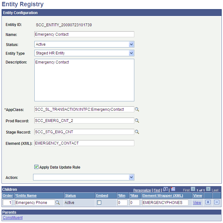
You can use the Entity Registry page to not only create new entities but also to maintain existing entities.
For example, you can use the page to:
Specify that you do not want to apply a data update rule to an entity.
Change the application class that handles the entity data.
Change the staging or production table record.
Require a property to be included inside the incoming or the outgoing xml message.
Generate the schema based on specific entity settings that you can later use to configure the messages in Integration Broker.
Generate the base code for the entity based on the configuration provided.
Add entities as children, extending the entity tree.
Edit entity views.
Sync entities.
Entity Configuration
|
Field or Control |
Definition |
|---|---|
| Entity ID |
Displays the auto-generated unique ID. When you add a new entity type, this field displays the value NOID until you save the record. When you save the new entity, the field displays the ID that the system assigned to the entity. |
| Name |
Required. Enter the entity name. |
| Status |
Required. Enter the entity status. If you select Inactive, the system ignores the entity and its children. |
| Entity Type |
Select the entity type. The system prompts you with the entity types defined on the Entity Type page. |
| Description |
Enter the description of what the entity is used for. |
| AppClass (Application Class) |
Specify the application class that implements the entity's logic. Generally, this application class provides the properties, and adds any custom validation, pre-save, or fill logic. However, because it is an application class, this class can override any functionality from the base class. The delivered base classes are stored inside the application package called: SCC_COMMON:ENTITY (for instance StagedEntity, StagedHREntity, BasicEntity, ChildEntity, and WorkEntity application classes). The application class that you enter here extends these existing application classes depending on the entity type. Note: When creating a new entity, you can create an empty application class in Application Designer and enter its name here. Once the entity setup data is entered, you can select Generate Code in the Action field to generate the code that can be pasted inside the application class peoplecode. If the entity is of a type that supports a default class the application class will not be marked required, and if no application class is specified the default will automatically be used. The default can be overridden at any time by specifying an appclass here. |
| Prod Record (Production Record) |
Enter the name of the production record where the entity data is permanently stored. Note: This field appears only if you have indicated that the selected entity type will use production record. You indicate this on the Entity Type page. |
| Stage Record |
Enter the name of the stage record where the entity data is temporarily stored. Note: This field appears only if you have indicated that the selected entity type will use stage record. You indicate this on the Entity Type page. |
| Element (XML) |
Enter the element name that the system will use for this entity inside the XML messages. The name that you enter here should not match any other entity’s element name and cannot contain spaces. For example, for the delivered Emergency Contact entity name, we gave the element name EMERGENCY_CONTACT. |
| Apply Data Update Rule |
Select if you want to apply a data update rule to an entity. You use the Data Update Rule Entry page to define data update rules for an entity. Defining data update rules for an entity may require additional coding. Note: SCC_COMMON.ENTITY.AbstractEntity application class handles the basic logic for data update rules. For special cases, where rules could be subdivided by type, the logic resides in the particular entity's application class. Note: To populate an entity on the Data Update Rule Entry page, you must first select the Apply Data Update Rule check box for the entity on the Entity Registry page. Then, click the Refresh button on the Data Update Rule Entry page. Conversely, to remove an entity from the Data Update Rule Entry page, first deselect the Apply Data Update Rule check box for the entity. Then, click the Refresh button on the Data Update Rule Entry page. See Setting Up CTM. |
| Action |
You can select from the following actions:
See the “Selecting Actions on the Entity Registry Page” section for information about these actions. |
Selecting Actions on the Entity Registry Page
|
Field or Control |
Definition |
|---|---|
| Edit Entity View |
Select to access the Entity Registry Views page. Entity views allow the creation of subsets of entity meta-data. |
| Edit Properties |
Select to access the Entity Properties page. The Entity Properties page enables a finer control of entity properties through a UI controlled meta-data. Note: This action is available only if you have indicated that the selected entity type will use properties. You indicate this on the Entity Type page. |
| Generate Code |
Select to access the Entity Code Generation page after you complete the entity registry setup. The Entity Code Generation page enables you to configure and generate the application class code. See Setting Up Entity Registry, “Generating the Entity Code.”. |
| Generate XSD |
Select to access the Entity Schema page. The Entity Schema page displays the generated schema that you can paste inside an Integration Broker message schema. Note: While you can generate schemas from any entities, it is useful only for entities that a service directly calls. In other words, it depends on what the base entity needs from a service that uses the entity. For example, the Names entity (which is a child of the Constituent entity) is not directly used. Therefore, if you extended the Names entity or make modifications to it, do not generate the XSD for Names, but instead generate the XSD for its root entity (that is, Constituent). Note: It is useful to select this action when the root entity is modified. For instance, select this action for a parent entity, if you add or remove its children entities inside the Children grid. See PeopleSoft Integration Broker for more details on schemas. |
| Sync Entity |
Select this action to run the sync process. A pop-up appears to indicate that the sync process has completed. The sync process:
You should run the sync process after creating or modifying an entity or after you have set up or changed the underlying records for the entity. You must run the sync process before you generate any entity code or schemas. Therefore, the sync process is automatically triggered when you save the Entity Registry component or select an Action of Generate Code or Generate XSD (selecting these actions would also trigger a save) when one of the following conditions is met:
The sync process is supported based on entity type. Currently, all delivered entities, except Custom, support syncing. Note: The Sync Entities action is available only if you have specified a Sync AppClass for the entity type. If you have selected the Allow Properties option but did not specify a Sync AppClass on the Entity Type page, even then the system does not display the action. Note: The sync process does not reset the settings you have entered on the Entity Properties and the Entity Property Details pages. The process only synchronizes the entities and field names with the underlying records. Warning! If you add, remove, or rename a field of an underlying record, then all the entities using the record must be re-synchronized. The Sync process will handle property associations. After the sync, you should update the code to incorporate the changes the sync process had made. The easiest way to do this is to simply regenerate the code and re-add any customizations. Note: Properties that are specified on the entity definition that do not exist at all in the code will be automatically handled. If the property maps to a field on the record that will be taken care of. If the property is completely new it will be stored in a hash table. Either way the safest way to access that data is by using the new methods getProperty and setProperty. Defaults all use these methods to access properties. You can also manually update the code. To do this, remove database references from fields that are no longer part of the record. Add properties for new fields that should now be in the property list. |
| Unit Test |
Select to access the Entity Unit Tests page. The page lists the unit tests that you have created for the entity and enables you to run the unit tests. |
| View Hierarchy |
Select to view the children hierarchy for the entity. |
Children
Use the Children grid to list the entity names that are children of the main entity name. For example, in the preceding Entity Registry page screen shot, the Emergency Contact is the main entity and the Emergency Phone is a child. A parent-child relationship does not imply dependency. Each entity can exist independently and is sometimes used as such, that is, you can directly create an instance of Emergency Phone entity and use it to modify an Emergency Phone Number, without needing the parent. Entity logic is encapsulated inside the entity and is unknown from the related entities.
Warning! To create parent-child relationships, a good understanding of the data structure is required.
|
Field or Control |
Definition |
|---|---|
| Order |
Specify the sequence of the child entities in the XML schema. |
| Entity Name |
Enter the name of the child entity. The system prompts you with only the entities that are configured with an entity type defined as Entity Type Children for the parent entity type. For example, suppose on the Entity Type page, for Staged Entity type you have added two entity type children, Staged Entity and Custom. Now, suppose Academic Program and Academic Plan entities have an entity type of Staged Entity on the Entity Registry page. Two other entities - Academic Interests entity has an entity type of Custom and Prospect Program entity has entity type of Basic Entity on the Entity Registry page. Therefore, on the Entity Registry page you can add Academic Plan and Academic Interests as child entities for the Academic Program entity. However, you cannot add Prospect Program entity as a child for the Academic Program entity. |
| Status |
Displays the status of the child entity. |
| Embed |
Specify how you want the XML messages to display the child entity data with the parent entity data. Select the Embed check box if you want the child entity data to be embedded in the parent entity data. This is useful for certain sibling record purposes where you do not want the XML to show the child at a separate level from the parent.
|
| Min |
Enter the minimum number of occurrences of this entity under the parent, which can be the number 0 or any number greater than 0. |
| Max |
Enter the maximum number of occurrences of this entity under the parent. Note: The number 0 means the maximum is unbounded, or any number greater than the min value can be used. |
| Element Wrapper (XML) |
Optional. Enter a value that the system can use as a tag to wrap all the child occurrences of this entity under the parent.
|
| View |
Click to access the Entity Registry page for the child entity. |
Parents
This region displays the parent entities. More than one parent can exist. Click the link to access the Entity Registry page for the parent.
Access the Entity Properties page (select Edit Properties in the Action field on the Entity Registry page).
Image: Entity Properties page (1 of 2)
This example illustrates the fields and controls on the Entity Properties page (1 of 2). You can find definitions for the fields and controls later on this page.
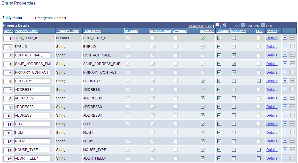
Image: Entity Properties page (2 of 2)
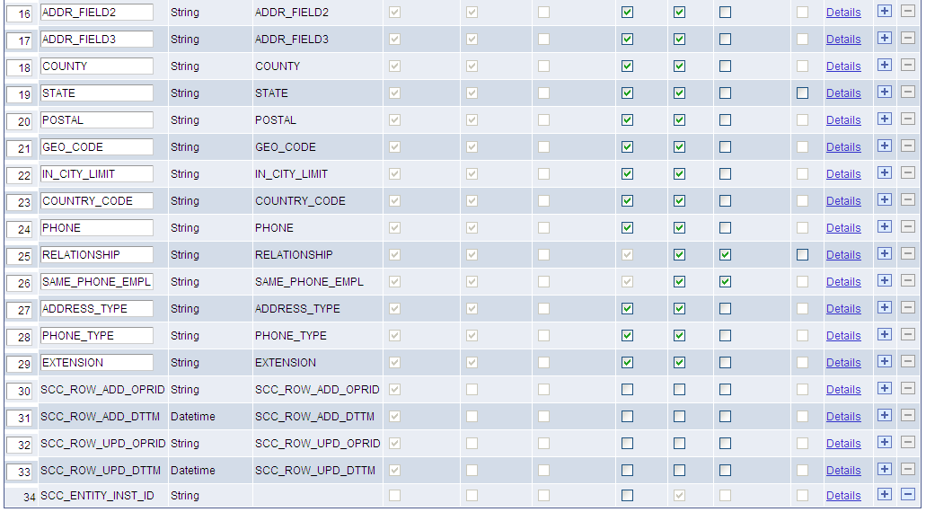
This example illustrates the fields and controls on the Entity Properties page (2 of 2). You can find definitions for the fields and controls later on this page.
The Entity Properties page enables you to define how a property should behave when its data is encoded as XML (for instance, when the system uses the property inside web services). A property is defined as an individual value on the entity that is controlled by the Entity Registry component. Properties are generally based on the fields of the underlying records (that is, staging record if it exists and production record). However, properties can exist that are independent of the underlying records. We refer to these independent properties as transient properties. You must write custom code to save or populate the transient properties. Entities can have an unlimited number of properties.
The system uses the properties, and not the fields of the underlying records, as the source of truth to drive the functionality of the underlying entity, and to generate the entity code and the schema.
|
Field or Control |
Definition |
|---|---|
| Order |
Order the properties as you want then to be displayed inside an XML message. |
| Property Name |
Indicates the property name on the entity object. By default, the property name matches the field name. You can change a property name, unless the property is already handled by the base application class, which causes the property to be read-only. Note: You cannot delete property names that match the fields in the staging record (if it exists) or in the production record. Note: Inside the delivered entities, the property name SCC_ENTITY_INST_ID is listed even though it is not included inside the underlying records (we refer to these extra properties as transient properties). The primary use for this transient property is to provide a unique identifier for a particular instance of an entity. When an error occurs, this ID enables the system to link an error to a specific entity instance. Warning! If you make any changes to the property name after the code has been generated, then you must either regenerate the code or manually update the property names to match the new name. For information on how to use property name SCC_ENTITY_INST_ID, see User Interface Considerations, “Error Handling.” |
| Property Type |
Indicates whether the property is a String, Number, Date, Datetime, or Time. If the property is based on a field, the system automatically determines the property type based on the field type. You cannot edit such a property type. Note: The Property Type field is enabled only when the entity is set up with the entity type Custom or when you add a new property name (transient property). Note: When the system triggers the Sync process, the process makes sure that the Property Type displayed for each property on this page matches the field type changes that may have occurred in the underlying records. Warning! If you make any changes to the property type after the code has been generated, then you must either regenerate the code or manually update the property data types to match the new type. |
| Field Name |
Displays the name of the matching field inside the underlying records. Only the sync process can enter and maintain this value. Note: A Field Name value appears only when the property is field based. Note: The sync process ensures that the correct Field Name value appears. |
| In Stage |
Indicates whether the Field Name is included in the stage record. Only the sync process can select or deselect this check box. Note: This field appears only if you have specified a stage record on the Entity Registry page. Note: The sync process verifies whether the field is still included inside the stage record. If this property changes, you will need to change the code in the get and set methods to match the changes. Example code for a property that is only in stage record: get PropertyName
/+ Returns String +/
If %This.STAGE_MODE Then
Return %This.data. PropertyName.Value;
End-If;
Return "";
end-get;
set PropertyName
   /+ &NewValue as String +/
   If %This.STAGE_MODE Then
      %This.data. PropertyName.Value = &NewValue;
   End-If;
end-set;
Warning! If you remove a field from both production and stage records, the Entity Properties page will still display the property. Properties are never removed and have to be manually deleted, to avoid changes to schema. Notice that after you manually remove the property in the code, the system enables the minus sign in the grid to allow you to delete the property. |
| In Production |
Indicates whether the Field Name is included in the production record. Only the sync process can select or deselect this check box. Note: The sync process verifies whether the field is still included inside the production record. If this property changes, you will need to change the code in the get and set methods to match the changes. Note: This field appears only if you have specified a production record on the Entity Registry page. Warning! If you remove a field from both production and stage records, the Entity Properties page will still display the property the Entity Properties page. Properties are never removed and have to be manually deleted, to avoid changes to schema. Notice that after you manually remove the property in the code, the system enables the minus sign in the grid to allow you to delete the property. Example code for a property that is only in production record: get PropertyName
/+ Returns String +/
If not %This.STAGE_MODE Then
Return %This.data. PropertyName.Value;
End-If;
Return "";
end-get;
set PropertyName
   /+ &NewValue as String +/
   If not %This.STAGE_MODE Then
      %This.data. PropertyName.Value = &NewValue;
   End-If;
end-set
|
| Attribute |
Attributes from the Common Attribute Framework can be accessed as properties on an entity. This allows attributes to be treated more like fields on a record. See the “Common Attribute Framework Integration” documentation later in this section. |
| Viewable and Editable |
When you select the Viewable check box, the system adds the property to any generated outgoing XML, JSON or Rules Engine message that includes the entity (the system does this using the toXMLNode method). This outgoing message from a system can either be a request message or a response message. When you select the Editable check box, the system parses the property from any incoming XML, JSON or Rules Engine message that it receives (the system does this using the fromXMLNode method). If the Editable check box is not selected, the system will ignore any incoming data. Note: While entities are used for services, it is not their only use. Options such as Viewable and Editable have implications outside of services (for instance, importing and exporting XML, JSON or Rules Engine data). Therefore, while request and response messages do make use of the Viewable and Editable options, these messages are not the only usage scenarios for the options. Note: If you do not select either the Viewable check box or the Editable check box, the property will not appear in the schema. Note: The values for transient properties are not stored, but the system can include these values inside the messages. Because at configuration time the sync process cannot tell if it should have an incoming or outgoing value or not, the Viewable and Editable options are always valid for transient properties. Note: The sync process, by default, selects the Viewable and Editable check boxes for every field except for fields that the system has programmatically marked to be ignored based on the entity type (for instance SCC_ROW_ADD_OPRID, SCC_ROW_ADD_DTTM, SCC_ROW_UPD_OPRID, and SCC_ROW_UPD_DTTM). You can manually select the Viewable and Editable check boxes for these ignored fields. |
| Required |
Indicates if the field is required. If the check box is selected, the system must populate the data into the field. The system will check whether the data exists for the field inside the XML or JSON messages during validation. When a property is marked as required, the system automatically selects and disables the Viewable check box. Selecting a field as required means it will be marked minOccurs 1 in the schema, that is, the field must be included in any occurrence of the XML. Note: For entities configured with an entity type that uses a stage record, the sync process, by default, selects the Required check box if the field is included in both production and stage records. If the field is only included in one of the underlying records, even it if is required in the record definition, the sync process does not mark the field as required. This is because the field may not be required in all circumstances. For entities configured with an entity type that does not use a stage record, the sync process, by default, selects the Required check box if the field is marked as required inside the production record. |
| LOV (List of Values) |
Select if you want to send the value description, with the value in the outgoing XML (the Viewable check box must be selected). The system enables this check box for only the fields that have list of values, that is field names defined with a prompt table or field names defined as translate fields inside the record definition in Application Designer. The system includes the description inside the outgoing XML message under a new tag labeled <name of the property Element (XML)_LOVDescr>. By default, this option uses the following logic to return the description:
For example, in the Emergency Contact entity, the production record is SCC_EMERG_CNT_2. If you want to include a description in the outgoing XML message for the COUNTRY property (which is a field with a prompt table), selecting the LOV check box will result in including the following tag inside the outgoing XML message: <COUNTRY_LOVDescr>, where COUNTRY is the Element (XML) name defined for the COUNTRY property. Suppose the COUNTRY value gets populated with USA. The LOVDescr tag will then contain: <COUNTRY_LOVDescr>United States</COUNTRY_LOVDescr>. The value United States corresponds to the DESCR field found inside the prompt table (COUNTRY_TBL) defined inside the SCC_EMERG_CNT_2 record for the COUNTRY field name. If you do not want to use the default logic, click the Details link and set the LOV Unique ID field on the Entity Property Details page. Note: The sync process enables the LOV check box only if the field is defined with a prompt table or defined as a translate field inside the record definition. The sync never selects or deselects the check box. Only you can manually select or deselect this check box. Note: The default logic returns the field description from the record that is being used. Therefore, if the service operation is using the stage record, it will evaluate the record definition for the stage record. If instead the operation uses the production record, it will use the field description stored inside the record definition for the production record. |
| Details |
Click to access the Entity Property Details page. |
| Last Synced |
Shows the last time this entity was synced. If the entity has not been synced since Bundle 27 (when last synced tracking was introduced), this date will not appear. Clicking the date time link will show the detail log for the sync. This log is identical to the one seen when viewing the details from the Entity Property Sync component. |
Common Attribute Framework Integration
Attributes from the Common Attribute Framework are treated as entity properties. By adding the properties and syncing the entity the new attributes appear as properties.
Attribute types map to equivalent entity property types:
|
Attribute Type |
Property Type |
|---|---|
|
Short Text, Text, Long Text, Yes/No, LOV |
String |
|
Number |
Number |
|
Date |
Date |
|
Time |
Time |
Repeatable maps to the list entity property list attribute.
If the Attribute Type is a list of values the Property LOV Unique ID is set.
For each attribute record a child entity is created. It is automatically added as a child. It is maintained and should never be accessed directly. This entity will never show up in XML/JSON and will not be accessible in the rules engine.
Access the Entity Property Details page (click the Details link on the Entity Properties page).
Image: Entity Property Details page
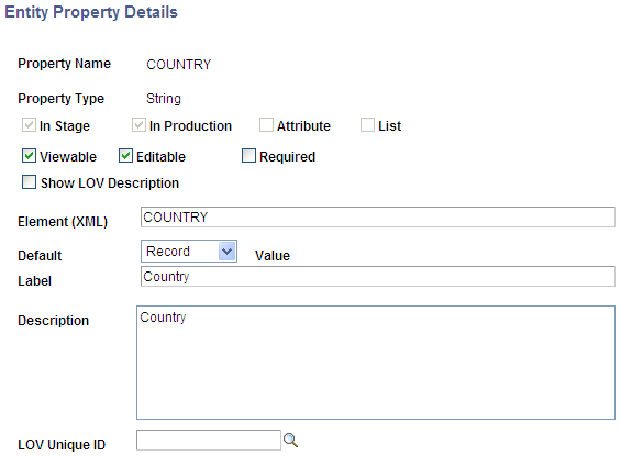
This example illustrates the fields and controls on the Entity Property Details page. You can find definitions for the fields and controls later on this page.
|
Field or Control |
Definition |
|---|---|
| List |
If this check box is selected, the property is treated as a list. This supports repeatable attributes. Non-field based properties can also be marked as lists, in which case they are treated as arrays in the entity application class. |
| Show LOV Description |
This check box is the same as the LOV check box that appears on the Property Details grid of the Entity Properties page. When one is selected, the other one is also selected. They both have the same purpose. |
| Element (XML) |
Indicates the label for the XML tag name used for this property. This is the tag that the system uses in the XML schema of the incoming and outgoing XML messages. Warning! If you change this value, you must select an Action of Generate XSD on the Entity Registry page to regenerate the schema and paste it inside the Integration Broker message schema. Note: The sync process, by default, sets this value to match the Field Name. |
| Default |
Define the default value. There are three types of defaults:
Note: The sync process always sets this value to Record. |
| Label |
Indicates the label for the property as shown in the comments for the XML schema. This is primarily a descriptive attribute. Note: If you want to see the new label in the schema, regenerate the schema. Note: The sync process sets this value with the default label defined in the field properties of the production record. |
| Description |
Indicates the description for the property as shown in the comments for the XML schema. This is primarily a descriptive attribute. Note: If you want to see the new description in the schema, regenerate the schema. Note: The sync process sets this value with the description defined for the field definition in Application Designer. |
| LOV Unique ID |
This field allows you to select a specific LOV prompt definition for the entity property to use. Note: Prior to bundle 29, the following fields existed: LOV Record, LOV Field, LOV Context. If these fields were populated prior to bundle 29, they will still be available/continue to work. However, for new entities (as of/after Bundle 29) you will use the LOV Unique ID field. |
| LOV Record, LOV Field, and LOV Context |
Note: As of bundle 29, these fields have been deprecated. Use the LOV Unique ID field instead. If these fields were populated prior to bundle 29, they will still be available. If you have selected the LOV check box on the Entity Properties page (or selected the Show LOV Description check box in the Entity Properties Details page) and do not want to use the default logic previously documented for the LOV column name in the Property Details grid, use the LOV Record, the LOV Field and optionally the LOV Context fields to define what description you want to see returned for the value selected. This setup is tightly coupled with the List of Values Setup component. Enter a record name as LOV Record and a field name as LOV Field, for which the system should retrieve the description value. For instance, in the Emergency Contact entity, suppose the outgoing XML uses the production record and you want to return the COUNTRY description, but do not want to use the prompt table defined inside the production record definition (COUNTRY_TBL record is defined as the prompt table for the SCC_EMERG_CNT_2 record and COUNTRY field name). In such a case, you can enter here some other record and field name associated with the prompt record you need. Note: The record you enter here is not the prompt table. It is the record and field name that is associated with the prompt table. Another use would be if you want to use the prompt table retrieved from the underlying record used, but want to use a specific description field like the short description field. By default, the code looks for the following fields until if finds one: DESCR, DESCRSHORT, DESCR30, DESCR100. If none of these works, it uses the first non-key field marked as a list box item. To reuse the same example from above, in that case, you could enter the name of the record (SCC_EMERG_CNT_2) and the field name (COUNTRY) associated with the prompt table and enter a LOV Context. Prior to this, you will first need to set up the LOV Context, on the List of Values Setup component, for the record SCC_EMERG_CNT_2 and field name COUNTRY. In the Self-Service Mode section of this component, you should specify that the Field Description to use for the prompt table COUNTRY_TBL and prompt field COUNTRY is the short description (DESCRSHORT). Note: When the Entity Registry component evaluates the List of Values Setup component, the system does not support the Administrative Mode. If you enter a LOV Record and LOV Field, the system checks whether the combination of the record and the field name has a configuration inside the List of Values Setup component. The logic is as follows:
|
Entity views allow the creation of subsets of entity meta-data. Entity views can only reduce access from what is specified at the base entity. So if a property is set to Viewable but not Editable, you cannot set it to Editable from a view, but Viewable can be turned on or off.
Access the Entity Registry Views page (select Edit Entity View in the Action field on the Entity Registry page).
Image: Entity Registry Views page
This example illustrates the fields and controls on the Entity Registry Views page. You can find definitions for the fields and controls later on this page.
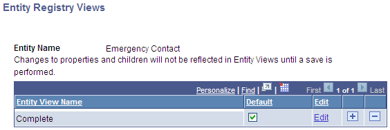
Every entity has a “Complete” view. The complete view always matches what has been set on the entity property and children. This view cannot be edited and is maintained during the sync process. A single view, per entity, is always marked default. The default view is used if no profile is selected, or if that entity does not belong to the current profile. Default also specifies the view assigned when a new entity is added to a profile. The default is used by all entity based services built prior to profiles existing (bundle 29), such as EWS and AAWS.
See Setting Up Entity Profiles.
The sync process maintains the entity view matching the entity properties and children. No data is currently logged for entity view syncs.
To create a new entity view, add a row on the Entity Registry Views page. You are taken to the Entity Registry View Details (SCC_ENT_VW2) page:
Image: Entity Registry View Details page (1 of 2)
This example illustrates the fields and controls on the Entity Registry View Details page (1 of 2). You can find definitions for the fields and controls later on this page.
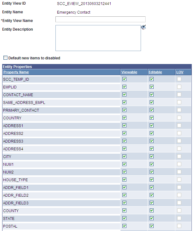
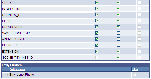
Image: Entity Registry View Details page (2 of 2)
This example illustrates the fields and controls on the Entity Registry View Details page (2 of 2). You can find definitions for the fields and controls later on this page.
Entity Properties
|
Field or Control |
Definition |
|---|---|
| Viewable and Editable |
You can select or deselect these check boxes on a per property/view basis. |
| LOV |
You can select or deselect this check box on a per property/view basis, but only if the LOV check box is available and selected for the property. |
Entity Children
|
Field or Control |
Definition |
|---|---|
| Hide |
Select this check box to hide entity children. The entities that are a direct child of the current entity (and any children of those entities) will not be shown. Note: Selecting this check box just hides the entity child; it does not prevent that child from being filled as part of the initial fill process. This avoids certain complications in the rules engine. |
Access the Entity Schema page (select Generate XSD in the Action field on the Entity Registry page).
Image: Entity Schema page
This example illustrates the fields and controls on the Entity Schema page. You can find definitions for the fields and controls later on this page.
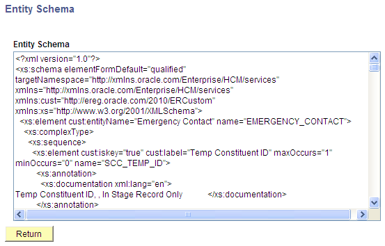
The system generates the schema based on the property settings. If the following settings are changed on the Entity Properties and Entity Property Details pages, you must regenerate the schema:
Element (XML)
Show LOV Description and LOV check box
In Stage
In Production
Required
List
Any changes made to the following property settings do not require regenerating the schema as their function is primarily descriptive:
Label
Description
You can paste the generated schema to the appropriate message name inside the Schema page ().
For information on schemas, see PeopleTools: Integration Broker.
Access the Entity Code Generation page (select Generate Code in the Action field on the Entity Registry page).
Note: This should only be done for entities where the application class is specified. Entities using the default application class approach have no need to do this.
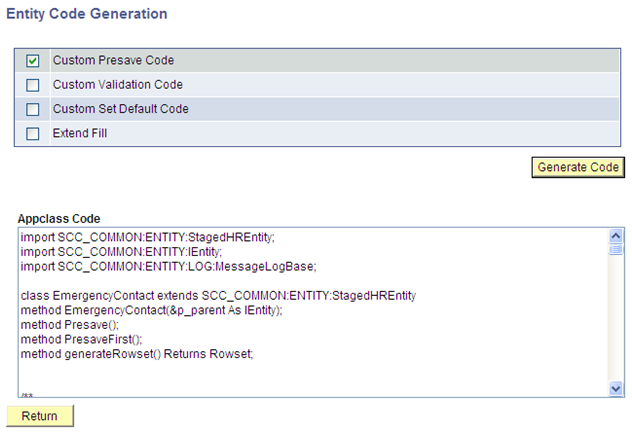
Image: Entity Code Generation page
This example illustrates the fields and controls on the Entity Code Generation page. You can find definitions for the fields and controls later on this page.
The system generates the code based on the property settings. If the following settings are changed on the Entity Properties and Entity Property Details pages, you must regenerate the code:
Property Name
Property Type
In Stage
In Production
Attribute
List
The four options that the grid displays are dynamic, based on the entity type and are coded in the Code Generation Appclass. Therefore, while these options are available in most of the delivered entity types, they are not static.
|
Field or Control |
Definition |
|---|---|
| Custom Presave Code |
Select to add the methods preSave and preSaveFirst to the generated code. These methods are called as part of the preSave process.
|
| Custom Validation Code |
Select to add the methods Validate and validateFirst to the generated code.
|
| Custom Set Default Code |
Select to add an override for setDefault. Normally, setDefault is based on the field defaults specified on the record. It is recommended to first call %Super.setDefault() to set the default field values and then set any special overrides. |
| Extend Fill |
Select to override the method called Fill. The system runs this method when it takes data from a record and populates this data into an entity. You may need to override this method to modify data after retrieval from the database or to populate transient values. |
| Generate Code |
Click to generate the code template that can later be pasted directly inside the Application Class that you have specified on the Entity Registry page. Use Application Designer to paste the generated code. To generate the code, the system uses the staging record (if it exists) and the production record, the entity type, the entity property settings, and the selected code generation options. When you click the button, the sample code template is displayed inside the Appclass Code box. Note: Clicking this button is useful at the time of creating a new entity or if a change is made to an existing entity. For example, you could generate code when production or stage records are modified, or when properties are changed. |
To view the children hierarchy for an entity, select the View Hierarchy action on the Entity Registry page. Here is an example of an entity hierarchy:
Image: Entity Hierarchy example
This example illustrates the fields and controls on the Entity Hierarchy example. You can find definitions for the fields and controls later on this page.
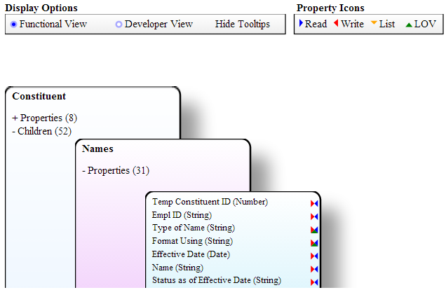
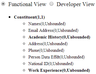
The hierarchy is dynamically drawn using HTML5 SVG. You can download the SVG, but only in Chrome and Firefox (not in Internet Explorer). IE8 does not support HTML5, so it shows an alternative list view. All other browsers can also view this using the View List link:
Image: Entity Hierarchy example list view
This example illustrates the fields and controls on the Entity Hierarchy example list view. You can find definitions for the fields and controls later on this page.
Display Options
|
Field or Control |
Definition |
|---|---|
| Functional View |
A view targeted at functional users. Shows entity names and property labels. |
| Technical View |
Targeted at developers. Adds Entity ID. Shows hidden properties and children (hidden children are transparent). |
| Hide Tooltips |
Allow or disallow tooltips. Tooltips appear over every entity name, property name, child link and property link to give extra details. Only available in SVG mode. |
SVG View
Click on properties(x) or children(x) to expand details.
List View
You can click on entities that appear in bold and these entities have children.
Whether child entities appear as expanded or collapsed is retained when switching back and forth between SVG and List View.