Virtual Lane Independence Through IP Subnetting
VL independence is enforced through IP networking by creating two separate IP
subnets for each datacenter and one IP subnet for communication between the two
datacenters.
For example, assume datacenter 1 has subnets A and B,
and datacenter 2 has subnets C and D, and subnet E is
the communication subnet between the two datacenters.
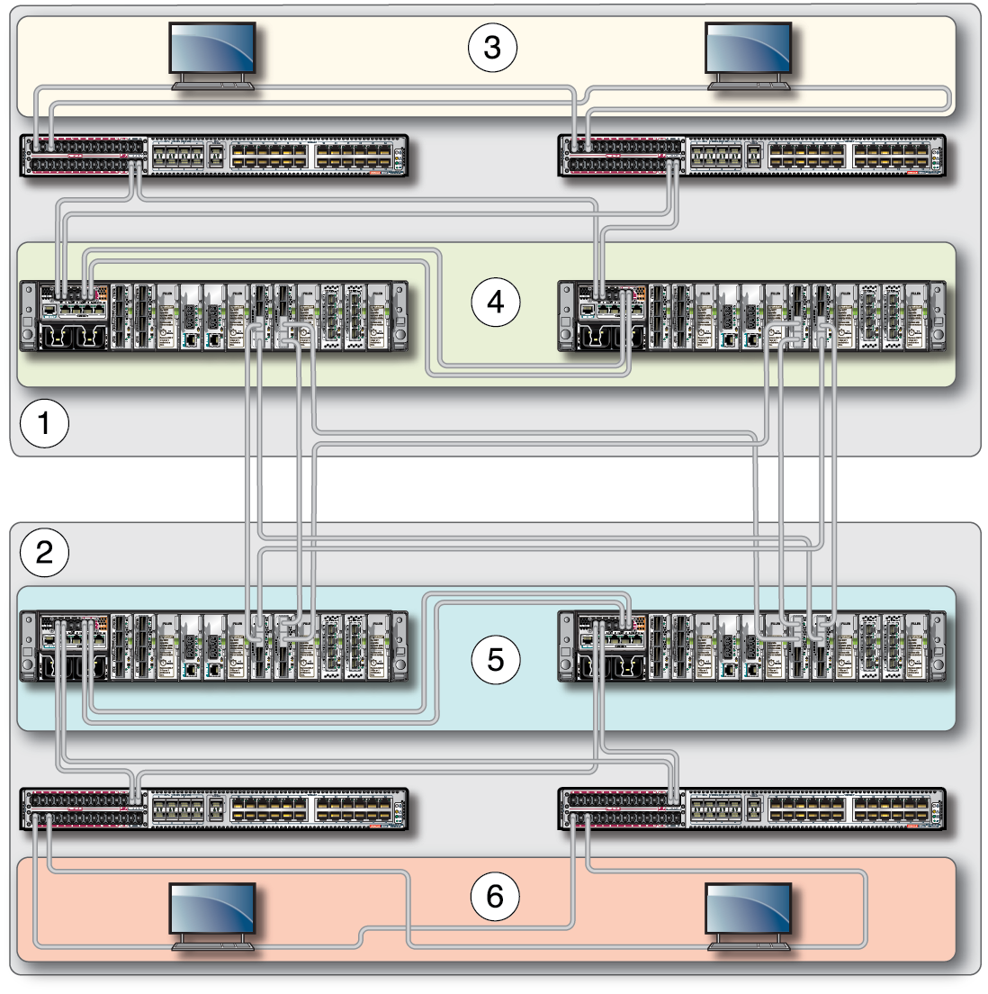
Within each datacenter, hosts and virtualization switches have their own IP
subnet, as shown in the following illustration.

|
|
|
1
|
Datacenter (shaded top area) consisting of hosts, leaf
switches, and virtualization switches.
|
|
2
|
Datacenter (shaded bottom area) consisting of hosts, leaf
switches, and virtualization switches.
|
|
3
|
IP Subnet, hosts (Subnet A)
One IP subnet for the hosts maps to an IPoIB link in
partition A and can be associated with
SL2.
The IP subnet for hosts is used for communication among
the hosts in one datacenter.
|
|
4
|
IP Subnet, virtualization switches (Subnet B)
One IP subnet for the virtualization switches maps to an
IPoIB link in partition B and can be associated with
SL3.
The IP subnet for virtualization switches is used for
communication between the pair of virtualization switches in
one datacenter. If communication between virtualization
switches is not required, these subnets can be left
undefined.
|
|
5.
|
IP Subnet, hosts (Subnet C)
One IP subnet for the hosts in the second datacenter maps
to an IPoIB link in partition C and can be associated with
SL2. This subnet is
conceptually the same as datacenter 1, but the IP subnet and
partition key must be unique to the second datacenter.
|
|
6.
|
IP Subnet, virtualization switches (Subnet D)
One IP subnet for the virtualization switches in the
second datacenter maps to an IPoIB link in partition D and
can be associated with SL3. This
subnet is conceptually the same as datacenter 1, but the IP
subnet and partition key must be unique to the second
datacenter.
|
|
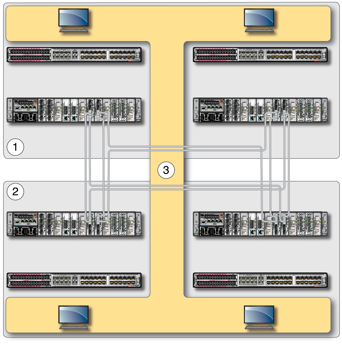
Between both datacenters, hosts in different datacenters can communicate over
the single communication subnet as shown in the following illustration.

|
|
|
1
|
Datacenter (shaded top area) consisting of hosts, leaf
switches, and virtualization switches.
|
|
2
|
Datacenter (shaded bottom area) consisting of hosts, leaf
switches, and virtualization switches.
|
|
3
|
IP Subnet, common subnet for host communication between
datacenters (Subnet E)
One IP subnet maps to an IPoIB link in partition E
associated with SL0.
|
|

