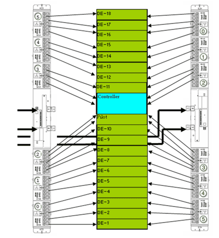
The wiring diagram for cabling a single-phase power distribution unit (PDU) shows power cord connections between the PDUs and the Oracle FS System components that are load balanced between the PDU outlet groups.
The wiring diagrams for PDU cabling and the current load shown is representative and includes Drive Enclosures, two Controllers, and two Pilots. Different component configurations within an Oracle FS System provide different results. For example, Drive Enclosures with SSDs have a lower power usage than Drive Enclosures with HDDs.
The wiring diagram illustrates the cabling of a single PDU. The second redundant PDU must be cabled identically. Cable connections to the PDU must be managed so that no outlet group exceeds 20A. The PDU groupings are reversed from one side to the other. From the back of the system, the PDU on the right are grouped 0 to 5 from the top of the rack to the bottom. The PDUs on the left are grouped 5 to 0 from the top of the rack to the bottom.
Figure 1: Wiring Diagram: Single-phase PDU cabling