The types of internal cables for the Oracle FS System are summarized in the sections below.
Private Management Network Cables
|
Cable |
Color |
Cable path |
Cable length |
Quantity |
Example |
|---|---|---|---|---|---|
|
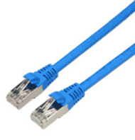
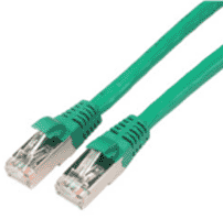
Ethernet CAT6a |
Blue |
Connects the Pilot 1 NET 0 port to the Pilot 2 NET 0 port Connects the Pilot 1 NET 2 port to the Pilot 2 NET MGT port Connects the Pilot 1 NET MGT port to the Pilot 2 NET 2 port |
9.84 feet (3 m) |
Three |
 |
|
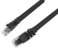
Serial RJ45 rollover |
Black |
Connects the Pilot 1 SER MGT port to the Pilot 2 SER MGT port |
6.6 feet (2 m) |
One |
 |
|
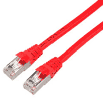
Ethernet CAT6a |
Red |
Connects the NET 1 ports of the Pilots to the NET 3 ports of the Controllers |
9.84 feet (3 m) |
Two |
 |
|
Ethernet CAT6a |
Green |
Connects the Controller 1 NET 2 port to the Controller 2 NET 2 port Connects the Controller 1 NET MGT port to the cluster interconnect (< - - - >) port of Controller 2 Connects the cluster interconnect (<- - ->) port of Controller 1 to the Controller 2 NET MGT port |
9.84 feet (3 m) |
Three |
 |
SAS Cables for Connecting the Controllers
|
Cable |
Color |
Cable path |
Quantity |
Cable length |
|---|---|---|---|---|
|
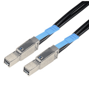
Mini-SAS HD to mini-SAS HD |
Black |
Connects Controller 1 to Controller 2 |
Two for a base system with one SAS HBA installed Four for a base system with two SAS HBAs installed Six for a performance system |
9.84 feet (3 m) |
Figure 1: Example of mini-SAS HD to mini-SAS HD cable connectors
SAS Cables for Drive Enclosure-to-Controller Connections
|
Cable |
Color |
Cable path |
Quantity |
Cable length |
|---|---|---|---|---|
|
Mini-SAS to mini-SAS HD |
Black |
Connects a Controller to a Drive Enclosure in the same rack |
Varies based on the configuration of the system |
9.84 feet (3 m) |
|
Mini-SAS to mini-SAS HD |
Black |
Connects a Controller to a Drive Enclosure that is in a separate rack |
Varies based on the configuration of the system |
19.69 feet (6 m) |
Figure 2: Example of mini-SAS to mini-SAS HD cable connectors
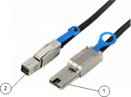
- Legend
-
1 Mini-SAS connector 2 Mini-SAS HD connector
SAS Cables for Drive Enclosure-to-Drive Enclosure Connections
|
Cable |
Color |
Cable path |
Quantity |
Cable length |
|---|---|---|---|---|
|
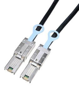
Mini-SAS to mini-SAS |
Black |
Connects a Drive Enclosure to another Drive Enclosure |
Varies based on the configuration of the system |
9.84 feet (3 m) |
Figure 3: Example of mini-SAS to mini-SAS cable connectors
Internal Power Cords
|
Cable |
Color |
Cable path |
Quantity |
Cable length |
|---|---|---|---|---|
|
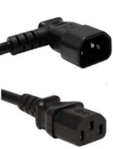
Power (C13 to C14 angled connector) |
Black |
Connects power cooling module 1 of a Drive Enclosure to PDU 1 Connects power cooling module 2 of a Drive Enclosure to PDU 2 |
Varies based on the configuration of the system |
3.28 feet (1 m) |
|
Power (C13 to C14 straight connectors) |
Black |
Connects power supply 1 of a Pilot to PDU 1 Connects power supply 2 of a Pilot to PDU 2 Connects power supply 1 of a Controller to PDU 1 Connects power supply 2 of a Controller to PDU 2 Connects power supply 1 of a MaxRep Replication Engine to PDU 1 Connects power supply 2 of a MaxRep Replication Engine to PDU 2 |
Varies based on the configuration of the system |
9.84 feet (3 m) |
Figure 4: Example of a power cord with C13 to C14 angled connectors