Power On the System
Set up a separate circuit and power outlet for each power distribution unit (PDU) as part of your site planning. These outlets must be located within reach of the PDU power cables.
Caution
Do not turn on any power circuits until the installation of all ordered hardware is complete and all internal cables are in place. Turning on the power to the system prematurely can prevent the system from starting up correctly.- Ensure that the PDU circuit breaker switches are in the “OFF” or “O” position.
- Connect the PDUs to the power source at the data center.
If the main circuit breakers at the data center are powered off, turn them on to supply power to the PDUs.
- Ensure that the power switches on the Drive Enclosures are switched on.
Figure 1: Power switches on the Drive Enclosures
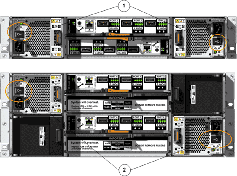
- Legend
1 The power switches on the DE2-24P Drive Enclosure 2 The power switches on the DE2-24C Drive Enclosure
- Configure the settings for the Ethernet interface on a laptop.Valid settings:
- Address
- 10.0.0.10
- Gateway
- 10.0.0.1
- Netmask
- 255.255.255.0
Note: You use the laptop to configure the management IP addresses for the Pilots. - Connect the laptop to the NET 3 port on Pilot 1.
Connecting a laptop to the NET 3 port on Pilot 1 ensures that Pilot 1 becomes the active Pilot when the system powers up.
Note: Both of the Pilots are clearly labeled as Pilot 1 and Pilot 2. In a standard configuration, Pilot 1 is the bottom Pilot in the rack. Pilot 2 is the top Pilot in the rack. - Ensure that all of the power cables plugged into the PDU are seated properly in their sockets. Improperly seated power cables can cause the amber LEDs to flash when the system is powered on. The flashing amber LEDs can be mistaken for a faulted power supply.
- Power on the PDU circuit breakers to apply power to the system.
Figure 2: PDU circuit breakers (example)
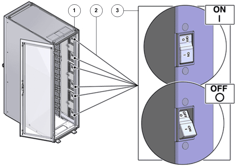
- Legend
1 Rack 2 Example of PDU circuit breakers 3 Toggle switch
Note: The Controllers and the Pilots automatically power on when you apply power to the system. - As the system powers up, verify that the Link LEDs display as steady on the NET 3 port on Pilot 1 and on the Ethernet port on the laptop.