4 Setting Up Cloud for IaaS
It contains the following sections:
4.1 Getting Started
This section helps you get started with this chapter by providing an overview of the steps involved in setting up the virtualization infrastructure. Consider this section to be a documentation map to understand the sequence of actions you must perform to successfully set up virtualized systems.
Note:
Click here to view a visual demonstration on how to discover OVM servers into the Cloud, configure storage for the Cloud, configure networking, and create server pools and Cloud zones using Oracle Enterprise Manager Cloud Control 12c.
-
Before you start monitoring and managing virtualization targets, you must register the Oracle VM Manager with Oracle Enterprise Manager. See Registering the Oracle VM Manager for details.
-
You can then discover one or more Oracle VM Server targets. See Discovering a Virtual Server for details.
-
Set up the storage infrastructure for the cloud. See Registering Storage Servers for details.
-
Configure networks and VLAN Groups. See Setting Up Networks for details.
If you are using Oracle VM Manager 3.3, you must configure the VLAN Interface. See Creating a VLAN Interface for Oracle VM Manager 3.3
-
Create a virtual server pool. See Creating a Virtual Server Pool for details.
-
Create a zone by grouping one or more server pools. See Creating a Zone for details.
Figure 4-1 shows the sequence of steps involved in setting up the virtualization infrastructure.
Figure 4-1 Setting Up the Cloud Infrastructure

4.2 Cloud Infrastructure Privileges
This section lists the actions that can be performed on various targets in the Infrastructure Cloud Home page when you:
-
Right click on a target in the left panel.
-
Select a target on the Members region on the parent target home page and then select the Action menu.
-
Select the Target menu of the corresponding Target Home page.
Table 4-1 Infrastructure Cloud
| Action Label | Multi-select / Single Select | Required Target State | Privileges Required |
|---|---|---|---|
|
Register OVM Manager |
Single |
Add any Target |
|
|
Setup |
Single |
View on Infrastructure Cloud |
|
|
Members |
Single |
Operator on Infrastructure Cloud |
Table 4-2 OVM Manager
| Action Label | Multi-select / Single Select | Required Target State | Privileges Required |
|---|---|---|---|
|
Members |
Single |
View On OVM Manager |
|
|
Edit |
Single |
Operator on OVM Manager |
|
|
Synchronize |
Single |
Full on OVM Manager |
|
|
Deregister |
Single |
Full on OVM Manager and all its sub targets |
|
|
Create Zone |
Single |
Operator on OVM Manager and Add any Target |
|
|
Create Virtual Server Pool |
Single |
Operator on OVM Manager and Add any Target |
|
|
Discover Virtual Server |
Single |
Operator on OVM Manager and Add any Target |
|
|
Manage Unowned Virtual Servers |
Single |
Operator on OVM Manager |
|
|
Manage Network |
Single |
Operator on OVM Manager |
|
|
Manage Storage |
Single |
Operator on OVM Manager |
|
|
Manage Storage Repository |
Single |
Operator on OVM Manager |
|
|
Manage Yum Repository |
Single |
Full on OVM Manager |
|
|
Manage NTP Configuration |
Single |
Full on OVM Manager |
Table 4-3 Zone
| Action Label | Multi-select / Single Select | Required Target State | Privileges Required |
|---|---|---|---|
|
Members |
Single |
View On Zone |
|
|
Edit |
Single |
Operator on Zone |
|
|
Delete |
Single |
Full on Zone |
|
|
Delete only from Enterprise Manager |
Single |
Full on Zone |
|
|
Deploy Assembly |
Single |
Operator on Zone and Add any Target |
|
|
Deploy Template |
Single |
Operator on Zone and Add any Target |
|
|
Deploy ISO |
Single |
Operator on Zone and Add any Target |
|
|
Deploy PXE |
Single |
Operator on Zone and Add any Target |
|
|
Import Virtual Machine |
Single |
Operator on Zone and Add any Target |
Table 4-4 Virtual Server Pool
| Action Label | Multi-select / Single Select | Required Target State | Privileges Required |
|---|---|---|---|
|
Members |
Single |
View On Virtual Server Pool |
|
|
Edit |
Single |
Operator on Virtual Server Pool |
|
|
Delete |
Single |
Full on Virtual Server Pool |
|
|
Delete only from Enterprise Manager |
Single |
Full on Virtual Server Pool |
|
|
Manage DRS / DPM Policies |
Single |
Operator on Virtual Server Pool |
|
|
Deploy Assembly |
Single |
Operator on Virtual Server Pool and Add any Target |
|
|
Deploy Template |
Single |
Operator on Virtual Server Pool and Add any Target |
|
|
Deploy ISO |
Single |
Operator on Virtual Server Pool and Add any Target |
|
|
Deploy PXE |
Single |
Operator on Virtual Server Pool and Add any Target |
|
|
Import Virtual Machine |
Single |
Operator on Zone and Add any Target |
Table 4-5 Virtual Server
| Action Label | Multi-select / Single Select | Required Target State | Privileges Required |
|---|---|---|---|
|
Edit |
Single |
Up |
Operator on Virtual Server |
|
Deregister |
Single |
Full on Virtual Server |
|
|
Delete only from Enterprise Manager |
Single |
Full on Virtual Server |
|
|
Start Maintenance |
Multiple |
Up |
Operator on Virtual Server |
|
Stop Maintenance |
Multiple |
Blackout |
Operator on Virtual Server |
|
Upgrade |
Multiple |
Full on Virtual Server |
|
|
Start |
Multiple |
Down |
Operator on Virtual Server |
|
Stop |
Multiple |
Up |
Operator on Virtual Server |
|
Restart |
Multiple |
Up |
Operator on Virtual Server |
|
Rediscover Virtual Server |
Single |
Full on Virtual Server |
|
|
Deploy Assembly |
Single |
Operator on Virtual Server and Add any Target |
|
|
Deploy Template |
Single |
Operator on Virtual Server and Add any Target |
|
|
Deploy ISO |
Single |
Operator on Virtual Server and Add any Target |
|
|
Deploy PXE |
Single |
Operator on Virtual Server and Add any Target |
|
|
Import Virtual Machine |
Single |
Operator on Zone and Add any Target |
|
|
Members |
Multi-select / Single Select:Single |
View on Virtual Server |
Table 4-6 Guest VM
| Action Label | Multi-select / Single Select | Required Target State | Privileges Required |
|---|---|---|---|
|
Edit |
Single |
Operator on Guest VM |
|
|
Delete |
Multiple |
Down, Metric Error |
Full on Guest VM |
|
Delete only from Enterprise Manager |
Multiple |
Full on Guest VM |
|
|
Migrate |
Multiple |
Up, Down |
Operator on Guest VM |
|
Move |
Single |
Down |
Operator on Guest VM |
|
Clone |
Single |
Up, Down |
Operator on Guest VM |
|
Save as Template |
Single |
Down |
Operator on Guest VM |
|
Start |
Multiple |
Down |
Operator on Guest VM |
|
Stop |
Multiple |
Up |
Operator on Guest VM |
|
Restart |
Multiple |
Up |
Operator on Guest VM |
|
Kill |
Multiple |
Up |
Operator on Guest VM |
|
Stop and Start |
Multiple |
Up |
Operator on Guest VM |
|
Suspend |
Multiple |
Up |
Operator on Guest VM |
|
Resume |
Multiple |
Operator on Guest VM |
|
|
Launch VNC Console |
Single |
Operator on Guest VM |
Table 4-7 Assembly
| Action Label | Multi-select / Single Select | Required Target State | Privileges Required |
|---|---|---|---|
|
Start |
Single |
Operator on Assembly |
|
|
Stop |
Single |
Operator on Assembly |
|
|
Delete |
Single |
Operator on Assembly |
|
|
Scale Up |
Single |
Operator on Assembly |
|
|
Scale Down |
Single |
Operator on Assembly |
|
|
Add Nodes |
Single |
Operator on Assembly |
Table 4-8 Tier
| Action Label | Multi-select / Single Select | Required Target State | Privileges Required |
|---|---|---|---|
|
Start |
Single |
Operator on Tier |
|
|
Stop |
Single |
Operator on Tier |
|
|
Scale Up |
Single |
Operator on Tier |
|
|
Scale Down |
Single |
Operator on Tier |
4.3 Registering the Oracle VM Manager
The Oracle VM Manager provides the user interface that allows you to create and manage zones, virtual server pools, virtual servers, and guest virtual machines. Before you use the Oracle VM Manager to manage virtualization targets in Enterprise Manager, you must register an existing installation of the Oracle VM Manager.
Note:
-
The Oracle VM Manager that you register with Enterprise Manager must be at least version 3.0.2 or higher.
-
The Oracle VM Manager must be associated with only one Enterprise Manager installation.
-
As a best practice, it is recommended that the Management Agent and the Oracle VM Manager are present on the same physical machine.
-
If you are registering Oracle VM Manager 3.3 or later, you must ensure that the Enterprise Manager for Oracle Virtualization (Oracle Virtualization) plugin 13.1.1.0 or a later version has been deployed on the Oracle Management Service and the Management Agent.
Prerequisites
-
If you are registering Oracle VM Manager 3.1.1 through 3.3, before you update the Oracle VM Manager URL, you must have configured tcps as described in Configure Secure TCP (TCPS) for Oracle VM Manager (Doc ID 1456338.1).
-
You must have imported the Oracle VM Manager certificate to the Agent keystore by following these steps:
-
Login as a root user and export the OVM Manager certificate
<JAVA_HOME>/bin/keytool -keystore <OVM_MANAGER_HOME>/ovmmCoreTcps.ks -exportcert -alias ovmm -file <file_loc_for_certificate> -
Login as an EM Agent install user and import the OVM Manager certificate <
AGENT_INSTANCE_HOME>/bin/emctl secure add_trust_cert_to_jks -trust_certs_loc <file_loc_for_certificate> -alias <alias_name>If the certificate is being imported for multiple Oracle VM Managers, you can specify multiple alias names.
-
-
If you are registering Oracle VM Manager 3.3, in addition to importing the Oracle VM Manager certificate, you must export the Oracle VM Manager WebLogic certificate and import the certificate to the Agent Keystore. See Importing the Oracle VM Manager WebLogic Certificate for details.
To register the Oracle VM Manager, follow these steps:
-
From the Enterprise menu, select Cloud, then select Oracle VM Infrastructure Home.
-
From the Infrastructure Cloud menu, select Register OVM Manager. The Add Oracle VM Manager page appears.
-
Enter the target name for the Oracle VM Manager instance to be registered.
-
Select the Management Agent to monitor and manage the Oracle VM Manager instance to be registered. It is recommended that the Management Agent (with Enterprise Manager for Oracle Virtualization plug-in (listed as Oracle Virtualization in Self Update) is present on the same machine where the Oracle VM Manager instance is running.
-
Enter the Oracle VM Manager URL. Refer to Note 1456338.1 (Configure Secure TCP (TCPS) for Oracle VM Manager) for details on configuring Oracle VM Manager for tcps access. The URL must be in one of the following formats:
- tcp://localhost:<port>. Example: tcp://localhost:54321(If the Oracle VM Manager version is 3.1.1 or greater, you can specify only the tcps URL.)-
tcps://<hostname:<port>. Example: tcps://server.domain:54322 -
Enter the Oracle VM Manager's Console URL. This is the URL to enable the VNC Console for the Guest VMs. For example,
https://ovmmgr.example.com:7002/ovm/console -
The URL must be in the following format:
https://<hostname>:<port>Note:
If you are registering Oracle VM Manager 3.3, this URL is used to connect to the Oracle VM Manager.
-
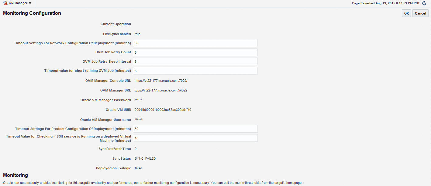
By default, data from Oracle VM Manager is automatically synchronized with Enterprise Manager at fixed intervals of time. If you do not wish to enable this option, you must disable the Automatic Synchronization checkbox and manually synchronize the data. For more details on the automatic and manual synchronization options, see Synchronizing the Oracle VM Manager Targets for details.
-
Enter the administrator user name and password to connect to the Oracle VM Manager URL provided in Step C. If you want to use separate credentials for managing Oracle VM Manager, check the Use Administration Credentials check box. If these credentials are not specified, the monitoring credentials are used by default.
-
Click Submit to register the Oracle VM Manager. You can now use the Oracle VM Manager to monitor and manage the virtualization targets in Enterprise Manager.
Registering Oracle VM Manager 3.4.X
Prerequisites
You must export the Oracle VM Manager WebLogic certificate and import the certificate to the Agent Keystore. See Importing the Oracle VM Manager WebLogic Certificate for details.
To register Oracle VM Manager 3.4.x, follow these steps:
-
From the Enterprise menu, select Cloud, then select Oracle VM Infrastructure Home.
-
From the Infrastructure Cloud menu, select Register OVM Manager. The Add Oracle VM Manager page appears.
-
Enter the target name for the Oracle VM Manager instance to be registered.
-
Select the Management Agent to monitor and manage the Oracle VM Manager instance to be registered. It is recommended that the Management Agent (with Enterprise Manager for Oracle Virtualization plug-in (listed as Oracle Virtualization in Self Update) is present on the same machine where the Oracle VM Manager instance is running.
-
Enter the Oracle VM Manager URL.
The URL must be in one of the following formats:
- tcp://localhost:<port>. Example: tcp://localhost:54321-
tcps://<hostname:<port>(As tcps specification is not required for Oracle VM Manager 3.4.x, enter a dummy URL such astcps://here.)Enter the Oracle VM Manager's Console URL. This is the URL to enable the VNC Console for the Guest VMs. For example,
https://ovmmgr.example.com:7002/ovm/consoleThe URL must be in the following format:
https://<hostname>:<port> -
By default, data from Oracle VM Manager is automatically synchronized with Enterprise Manager at fixed intervals of time. If you do not wish to enable this option, you must disable the Automatic Synchronization checkbox and manually synchronize the data. For more details on the automatic and manual synchronization options, see Synchronizing the Oracle VM Manager Targets for details.
-
Enter the administrator user name and password to connect to the Oracle VM Manager URL provided in Step C. If you want to use separate credentials for managing Oracle VM Manager, check the Use Administration Credentials check box. If these credentials are not specified, the monitoring credentials are used by default.
-
Click Submit to register the Oracle VM Manager. You can now use the Oracle VM Manager to monitor and manage the virtualization targets in Enterprise Manager.
4.3.1 Port Requirements for Oracle VM Manager Setup
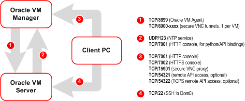
The ports required for the Web browser connection to Oracle VM Manager are 7002 and 15901. TCP 7002 is used by the Oracle VM Servers to connect to Oracle VM Manager. Oracle VM Manager, in turn, connects to the Oracle VM Servers through port 8899 for Oracle VM Agent communication, and port 6900 and up for secure VNC tunneling to virtual machines (one port per VM). Ports 7900 and up are used to allow Oracle VM Manager to open secure serial console tunnels to virtual machines (one port per VM) on the Oracle VM Servers. The Oracle VM Command Line Interface connects to Oracle VM Manager on port 10000. TCP ports 54321 and 54322 must be enabled for remote API access to the Oracle VM Manager core. Follow the guidelines of in the diagram below:
Figure 4-2 Oracle VM Manager Firewall Configuration
4.3.2 Updating the Oracle VM Manager URL
If you had Oracle VM Manager 3.0.x registered with Enterprise Manager previously and had upgraded it to higher versions 3.1.x or 3.2.1, you must update the Oracle VM Manager URL.
If you are upgrading to version 3.3, you must also import the WebLogic certificate. See Importing the Oracle VM Manager WebLogic Certificate for details.
Prerequisites
-
Before you update the Oracle VM Manager URL, you must have configured tcps as described in Note 1490283.1.
-
You must have imported the Oracle VM Manager certificate to the Agent keystore by following these steps:
-
Login as a root user and export the OVM Manager certificate
<JAVA_HOME>/bin/keytool -keystore <OVM_MANAGER_HOME>/ovmmCoreTcps.ks -exportcert -alias ovmm -file <file_loc_for_certificate> -
Login as an EM Agent user and import the OVM Manager certificate <
AGENT_INSTANCE_HOME>/bin/emctl secure add_trust_cert_to_jks -trust_certs_loc <file_loc_for_certificate> -alias <alias_name>
-
To update the Oracle VM Manager URL, follow these steps:
4.3.2.1 Importing the Oracle VM Manager WebLogic Certificate
Note:
This step is required for Oracle VM Manager versions 3.3 and 3.4Oracle VM Manager version 3.3 or later contains an internal Certificate Authority (CA) that is used to perform certificate-based authentication and to sign the SSL certificate that is used for the web-based user interface. Certificates are generated automatically when Oracle VM Manager is installed.
To export the Oracle VM Manager WebLogic certificate, login as the root user and enter the following command:
#/u01/app/oracle/ovm-manager-3/ovm_upgrade/bin/ovmkeytool.sh exportca > <file_loc_for_certificate>
To import the Oracle VM Manager Weblogic certificate to the Agent Keystore, login as EM Agent user enter the following command:
<AGENT_INSTANCE_HOME>/bin/emctl secure add_trust_cert_to_jks -trust_certs_loc <file_loc_for_certificate> -alias <alias_name>
Note:
If you are using a pre-3.4 Oracle VM Manager version, you must delete the first line in the <file_loc_for_certificate>: "libdir is /u01/app/oracle/ovm-manager-3/ovm_upgrade/bin/./../lib"before you can import the OVM Manager certificate.
4.3.3 Discovering and Promoting the Oracle VM Manager (Optional)
Automatic discovery is a process that detects hosts, Oracle VM Managers, and other targets so that they can be monitored and managed by Enterprise Manager. If you know the Oracle VM Manager instances in your environment, see Registering the Oracle VM Manager for details on registering them with Enterprise Manager. Discovery and promotion of Oracle VM Manager should be attempted if you want to scan your networks to discover unknown Oracle VM Manager instances.
- Log in to Enterprise Manager as a user with the Super Administrator role.
- From the Setup menu, select Add Target, then select Configure Auto Discovery.
- In the Network Scan-based Auto Discovery table, click Configure Network Scan Discovery in the Host and Oracle VM Manager row. The Network Discovery page appears. Use this page to search, browse, and create OVM Manager discovery specifications.
- Click Create. The Network Scan Discovery: Create page appears.
- Enter the Name and Description for the Discovery Specification. Click Add in the Network Scans region to select the Agent that is to be used perform the IP scan. For each Agent, specify the IP ranges for the scan. The following formats are supported: host name, IP address, and IP range. Use space to separate values.
- Use the Job Details tab on the Host Discovery Specification Create page to schedule the discovery IP scan, allowing you to start it immediately or at a later specified time. Use the Credentials section to enter preferred credentials for the host. You can choose from Preferred Credentials, Named Credentials, or New Credentials. The discovery IP Scan is run as root. It is required that you set privileged host credentials or named credentials that use Sudo.
- You can use the Host Discovery page to check the status of discovery and view newly discovered OVM Managers.
- After the target has been discovered, from the Setup menu, select Add Target, then select Auto Discovery Results. Enterprise Manager displays the Auto Discovery Results page where you can review discovered unmanaged targets and promote targets to be managed by Enterprise Manager for monitoring.
- On the Network-scanned Targets tab, the target discovery results are displayed in the table at the bottom. Select the OVM Manager target and click Promote. The OVM Manager Registration page is displayed. See Registering the Oracle VM Manager for details.
4.3.4 Upgrading Oracle VM Manager
The instructions to upgrade earlier versions of Enterprise Manager and Oracle VM Manager are covered in the following sections:
4.3.4.1 Upgrading to the 3.3 Release
To upgrade from earlier versions of Enterprise Manager and Oracle VM Manager to Oracle VM Manager 3.3, follow these steps:
- Upgrade Oracle Management Service to 12.1.0.4 and deploy the Oracle Virtualization plugin version 12.1.0.7 or higher.
- Upgrade Management Agent to 12.1.0.4 and the deploy the Oracle Virtualization plugin 12.1.0.7 or higher.
- Blackout the old Oracle VM Manager target.
- Upgrade the Oracle VM Manager to 3.3.1. For more information, see the Oracle VM Installation and Upgrade Guide for Release 3.3.
- Upgrade the Oracle VM Server to 3.3.1. For more information, see the Oracle VM Installation and Upgrade Guide for Release 3.3.
- Import the WebLogic certificate. See Importing the Oracle VM Manager WebLogic Certificate for details.
- Change the blackout status of the Oracle VM Manager target.
- Add or modify the target property if required. For example, Webservice URL using Edit Oracle VM Manager page.
4.4 Synchronizing the Oracle VM Manager Targets
Enterprise Manager can monitor the OVM Manager and the various virtualization targets registered with the OVM Manager. The targets registered with the OVM Manager must also be monitored targets in Enterprise Manager. If some targets have been created directly in OVM Manager, you can synchronize them in two ways:
4.4.1 Automatically Synchronizing the Oracle VM Manager Targets
You can enable this option when Oracle VM Manager is registered or when you Edit Oracle VM Manager. If the Automatic Synchronization option is enabled, all changes made in Oracle VM Manager are automatically reflected in Enterprise Manager at fixed intervals. The default interval is 1 minute. To change the default interval, follow these steps:
4.4.2 Manually Synchronizing the Oracle VM Manager Targets
When the Oracle VM Manager is registered, if the Automatic Synchronization option is enabled, for the targets created in Oracle VM Manager, corresponding targets are created in Enterprise Manager. If, this option is not enabled, you can manually synchronize the targets by following these steps:
4.5 Discovering a Virtual Server
A virtual server is a generic term used to describe a physical box which has virtualization software (hypervisor) running on it. A new virtual server can be provisioned by installing the OVM Hypervisor on a bare metal box. Before you add a virtual server to a server pool, it must be discovered.
The newly discovered Oracle VM Server contains some basic information about itself, and about any immediate connectivity to a network storage, but it is considered to be in an unconfigured state. After the storage and networking has been configured, the Oracle VM virtual servers are ready to be used as the infrastructure for cloud.
4.6 Rediscovering a Virtual Server
- From the Enterprise menu, select Cloud, then select Oracle VM Infrastructure Home.
- Right click on a Virtual Server target in the left panel and select Rediscover Virtual Server.
- A confirmation message appears. Click OK to rediscover the virtual server and discover any new NICs and LUNs that have been added.
4.7 Setting Up Networks
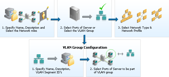
This section discusses creation and use of Oracle VM Networks. You can define a name or an alias for each logical network. When you have created your networks, you connect the physical network ports on Oracle VM Servers to the logical networks. Before you define the logical networks in Enterprise Manager, you have to review your physical network configuration that you intend to use, such as VLAN and subnet usage. Setting up an Oracle VM network involves:
- Generating MAC Addresses
-
Figure 4-5 Setting Up Networks
Note:
In Oracle VM Manager 3.3, VLAN Groups have been replaced with VLAN Interfaces. When you are configuring the VLAN Interface, you are prompted for the VLAN Segment IDs and the ports on which the interfaces are to be created.
4.7.1 Generating MAC Addresses
Virtual network interfaces (VNICs) are used to carry network traffic to virtual machines. You can generate MAC addresses that can be assigned to VNICs in a virtual machine. Specify a range of MAC addresses that need to be generated.
VLAN Group has been replaced with VLAN Interface and during Vlan interface configuration, it asjs VLAN Segment ID's and then Select Ports of Servers where the Interfaces to be created"
Note:
MAC addresses must be unique across all Oracle VM Managers in the data center.
To create MAC Addresses, follow these steps:
- From the Enterprise menu, select Cloud, then select Oracle VM Infrastructure Home.
- Right click on an OVM Manager target from the left panel and select Manage Network.
- Click the Virtual Network Interface Card Manager tab.
- Click Generate. In the Generate MAC Addresses pop-up window, you are prompted to specify an initial MAC address in 3 sets of 3 characters. This is a two-digit number for the Initial MAC Address. Click OK to return to the previous page. You can now use these VNICs while creating virtual machines.
Note:
If you are using 3.4 or later versions of Oracle VM Manager, enter the From and To range in the Dynamic MAC Address field and click Apply Range. This range will then be used to create MAC addresses as needed in future deployments.4.7.2 Configuring a VLAN Group for Oracle VM Manager 3.2 or Earlier Versions
Note:
Configuring a VLAN Group is an optional feature. If VLANs exist in your physical network, you must follow the steps in this section to use them in the cloud.
VLAN (Virtual Area Network) is a mechanism to virtualize network interfaces across subnets and physical location so that they appear to be on a single confined LAN. This concept is used to isolate (and group) the network traffic across these distributed interface, which enables secure network traffic within such nodes.
You can create multiple virtual LAN (VLANs) on the same NIC port. Each VLAN is an independent logical network operating with other VLANs over the same physical connection. Configuring VLANs involves creating one or more VLAN Groups, each of which contain multiple VLANs segments.
Each VLAN is assigned a distinct VLAN identification. The VLAN ID is used by an attached VLAN switch to segregate traffic among the different VLANs operating on the same link. Once a VLAN is configured, it functions exactly like a separate physical connection. VLANs need to be configured in the physical switches before you use them. To create a VLAN group, follow these steps:
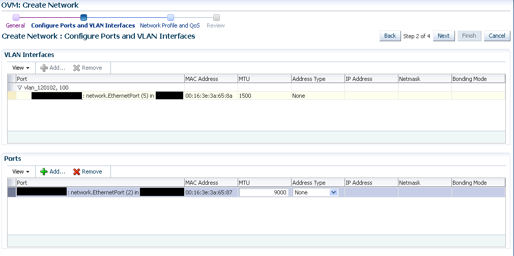
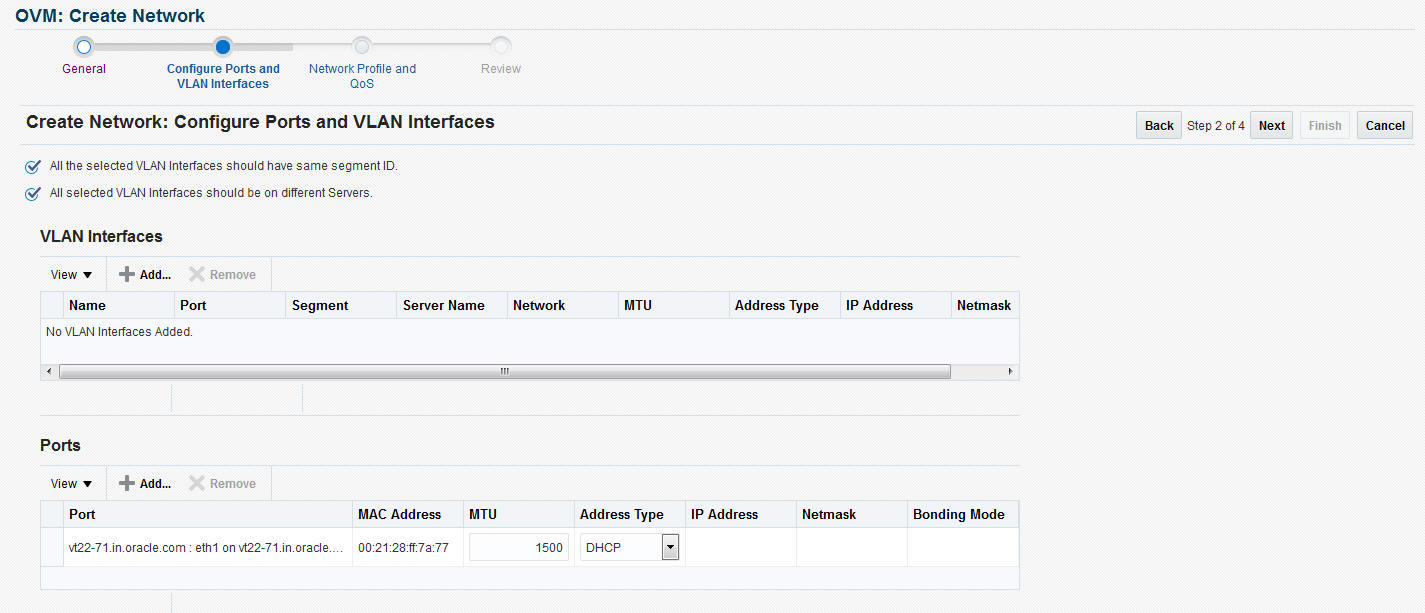
4.7.3 Creating a VLAN Interface for Oracle VM Manager 3.3
Note:
Configuring a VLAN Interface is an optional feature. If VLANs exist in your physical network, you must follow the steps in this section to use them in the cloud.
VLAN (Virtual Area Network) is a mechanism to virtualize network interfaces across subnets and physical location so that they appear to be on a single confined LAN. This concept is used to isolate (and group) the network traffic across these distributed interface, which enables secure network traffic within such nodes. VLANs are divided into segments that are usually tagged with an ID.
To manage network traffic tagged for different VLAN IDs, a separate VLAN or virtual interface can be created for each VLAN ID. When creating different logical networks in Oracle VM Manager, these VLAN interfaces can be attached to different networks to specify the type of traffic that belongs to a particular VLAN ID.
If your network is configured to support VLANs, you should define interfaces for your different VLAN IDs on each of your servers, so that you are able to define Oracle VM networks that take advantage of VLAN separation.
You can create multiple virtual LAN (VLANs) on the same NIC port. Each VLAN is an independent logical network operating with other VLANs over the same physical connection. Configuring VLANs involves creating one or more VLAN Interfaces, each of which contain multiple VLANs IDs.
Each VLAN is assigned a distinct VLAN identification. The VLAN ID is used by an attached VLAN switch to segregate traffic among the different VLANs operating on the same link. Once a VLAN is configured, it functions exactly like a separate physical connection. VLANs need to be configured in the physical switches before you use them. To create a VLAN Interface, follow these steps:
4.7.3.1 Viewing the VLAN Interfaces
To view the VLAN Interfaces that have been added, click the VLAN Interfaces tab on the Network page. The VLAN Interfaces are listed with the following details:
-
Name: The name of the VLAN Interface that is created.
-
Port: The network port on which the VLAN Interface has been assigned.
-
Segment: The VLAN ID assigned to the VLAN Interface.
-
Server: The server where the VLAN Interface is located.
-
Network: The network to which the VLAN Interface is attached.
-
MTU: The MTU value for the VLAN Interface.
-
Address Type: The network address assignment type. This can be Static, Dynamic, or None.
-
IP Address: The IP address allocated to the VLAN Interface.
-
Netmask: The netmask applied to the VLAN Interface.
4.7.3.2 Editing a VLAN Interface
To edit a VLAN Interface, follow these steps:
- Select the VLAN Interface you wish to edit from the list of VLAN Interfaces and click Edit.
- In the Edit VLAN Interface page, you can edit the MTU setting and the Address Type. If you select Static type, you can specify the IP Address and the Netmask.
- Click OK to save the changes and return to the previous page.
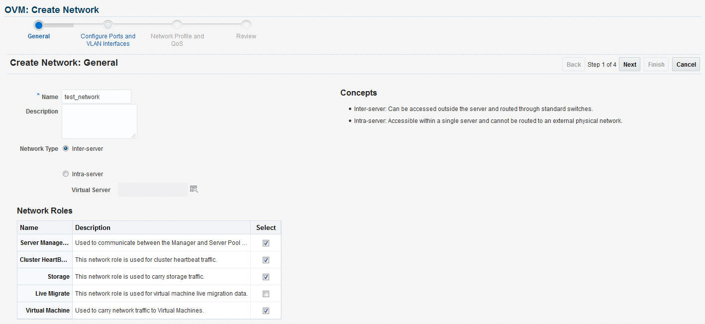
4.7.4 Creating Networks
A network is a grouping of Oracle VM virtual server physical NIC ports. This section describes the procedure to create a logical network.
Prerequisites
-
If you choose to associate a network profile with the network, then the network profile must be created before the network is created. A network profile stores the network interface configuration (IP address, subnet mask, host name, DNS servers) that is allocated to network interfaces of newly provisioned virtual machines.
Follow these steps to create a logical network:
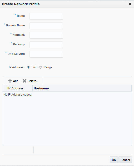
4.8 Creating a Network Profile
A network profile is used to automate assignment of IP addresses to guest virtual machines. A network profile is a list of IP address along with host names. It defines a set of IP addresses, their associated host-names, and common networking attributes for them.
To create a network profile, follow these steps:
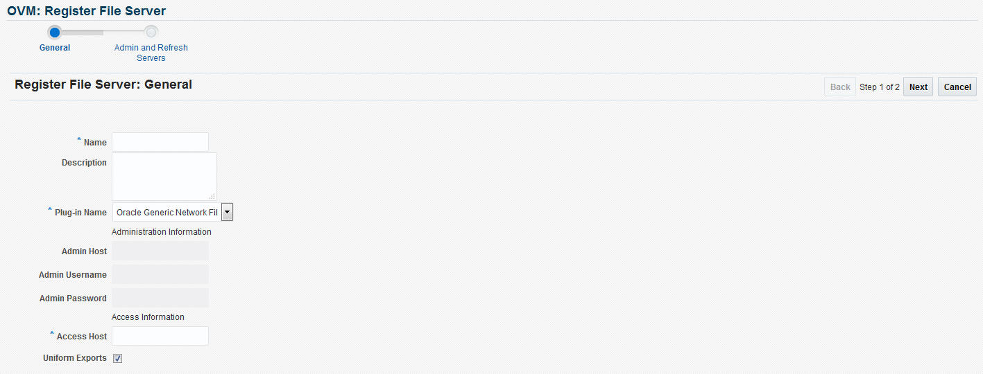
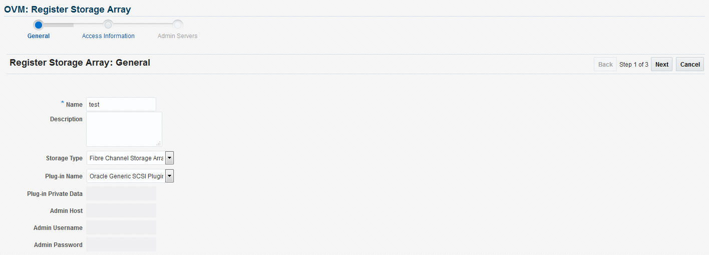
4.9 Registering Storage Servers
You can create external storage elements like storage servers, file systems, and LUNs. An external storage element is created on dedicated storage hardware such as a server configured for NAS offering NFS shares. The server on which the storage element is present must be accessible by the Oracle VM Servers through a fibre channel or ethernet network. You can configure a virtual server pool with multiple such external storage devices.
Figure 4-10 Creating Storage Servers and File Systems
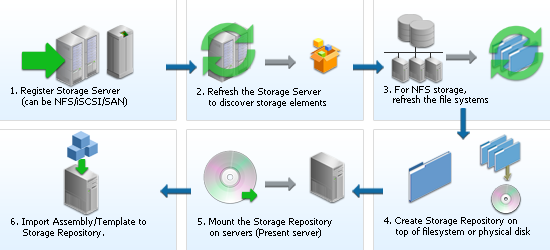
To set up a storage server, follow these steps:
4.9.3 File Server Details
Click a File Server link to view the Details page. This page contains the following tabs:
-
General: A list of Administration Servers is displayed. An Administration Server is a virtual server on which the storage plug-in has been installed. You can add an Administration Server or delete an existing one.
In the Configuration region, the storage server details are displayed. Click Edit to modify details such as Name, Description, and the name of the Access Host which provides the external storage.
In the Storage QOS Mapping region, map the storage type defined by the Cloud Administrator to the QOS defined by the Storage Server.
-
Refresh Servers: For non-uniform NFS file system exports, you can specify the servers that need to be refreshed. Click Add. The Refresh Servers dialog box is displayed. Click Select Servers, choose one or more servers from the list and click Select. Click OK to refresh the servers.
-
File Systems: A list of file systems is displayed. You can do the following:
-
Select a file system from the list and click Edit. You can modify the name and description of the file system.
-
Select a file system and click Delete. A confirmation message is displayed. Click OK to delete the file system.
-
Select one or more file systems and click Refresh. A confirmation message is displayed. Click OK to refresh the file system.
-
-
Access Groups: Shows the mapping between Refresh Servers and File Systems (Exports). You can Create, Edit, or Delete an Access Group.
4.9.4 Storage Array Details
Click a Storage Array link to view the Details page. This page has four tabs:
-
General: Provides general information on the storage array. A list of administration servers is displayed in the Administration region. An Administration Server is a virtual server on which the storage plug-in has been installed. You can add an Administration Server or delete an existing one.
In the Configuration region, the storage server details are displayed. Click Edit to modify the Name and Description.
-
Physical Disks: Displays a list of all the physical disks on the storage array. Depending on the type of storage connector (You can Create, Clone, Edit, Resize (resize or extend the physical disk), Rescan (refreshes the physical disk), Delete, and Create File System (create OCFS2 file system on the physical disk).
Note:
The operation allowed depends on the type of storage connect plug-in that has been installed. For example, if the generic storage connect plug-in has been installed, you cannot perform a Create operation on the physical disks.
-
Access Group: Shows the mapping between Storage Initiators and Physical Disks. You can Create, Edit, Present / Unpresent Access Group (Add or Delete physical disk), and Delete access group.
-
Volume Group: Displays the volume group available for this storage server.
4.9.5 Local File Server Details
Click on a Local File Server link to view the Details page. This page contains the following tabs:
-
General: The configuration details of the selected Local File Server including the Administration Host, Plug-in Name, and so on are displayed.
-
File Systems: You can edit or refresh a file system in the list. Select a file system from the list and click Edit. You can modify the name and description of the file system.
To refresh, select a file system from the list and click Refresh. Select the name of the virtual server and click OK to refresh the file system.
4.10 Creating a Storage Repository
A storage repository is virtual disk space on top of physical storage hardware, made available to the Oracle VM Servers in a server pool or various server pools. It defines where Oracle VM resources may reside. Resources include virtual machines, templates for virtual machine creation, virtual machine assemblies, ISO images, shared virtual disks, and so on.
After you have created the storage server, you can assign these storage resources to the server pools in a zone by creating a storage repository.
To create a storage repository, follow these steps:
4.10.1 Performing Administrative Operations on a Storage Repository
After the storage repository has been created, you can perform a number of management operations on it. The listing of storage repositories depends on the server pool selection. If you select server pools, you see all the storage repositories. If you select an individual server pool, only the storage repositories related to that server pool appear. You can perform the following operations:
-
Edit: Select a repository and click Edit. You can modify the name and description or release the ownership of the repository. Click OK to save the changes.
Note:
If you are editing a storage repository that has been created on a physical disk, you can change the server pool with which the storage repository is associated. To change the server pool, in the Edit dialog box, click the Search icon next to the Server Pool field, select a different server pool and click OK.
-
Delete: Select a repository and click Delete. All the contents of the selected repository along with its associations will be deleted.
-
Auto-Refresh: Select this option to enable Auto-Refresh and periodically refresh and update the file system size of all storage repositories. In the dialog box that appears, select the Enable check box and specify the Interval at which the file system size is to be refreshed.
Note:
As the Auto-Refresh option locks the repositories, you must use this option when no deployment operations are scheduled.
4.11 Presenting the Storage Repository
After you have created the storage repository, you can propagate it to one or more server pools. When the storage repository is prepared and created, it still must be made available for use by your virtual servers before it can be used. Typically you present the storage repository to all the virtual servers in the server pool.
To present a storage repository to server pool, follow these steps:
4.12 Importing Assemblies, Templates, and Virtual Disks into the Storage Repository
A storage repository associated with an Oracle VM server stores binary components associated with an Oracle VM servers. The following software components can be stored in the storage repository:
The Oracle Virtual Assemblies, Oracle VM Templates and ISO images need to be imported into the storage repository before guest virtual machines can be created using them. Follow these steps to import software components into the storage repository:
Note:
Creation Time is not displayed if you are using 3.4 or later versions of Oracle VM Manager.4.12.1 Creating a Repository Export (Optional)
You can configure the virtual server to enable third party applications to back up the contents of the storage repository.
Prerequisites
-
The Repository Exports feature is available only for storage repositories based on physical disks and at least one server must have been presented to the repository.
-
The virtual server must be configured to provide an NFS share to access the contents of the repository.
-
The virtual server must be in a clustered server pool and have the OCFS2-based storage repository presented to it.
To create a repository export, follow these steps:
- Click the Repository Exports tab in the Storage Repository Details page.
- Click Create. The Create Repository Export window appears.
- Enter a name of the host which is used to mount the contents of the storage repository to the Export Server.
- Specify the options to restrict access to the respository. For Linux systems, the default is
rw,async,no_root_squash. - Click Add in the Export Server(s) region. Select one or more virtual servers on which the storage repository is to be presented and click Select.
- Click OK to submit the job and return to the Storage Repository Details page.
4.13 Using Self Update to Download Oracle VM Templates and Virtual Assemblies
You can download the preconfigured assemblies and templates from the Self Update Console by following these steps:
- Log in to Enterprise Manager as a user with the
EM_CLOUD_ADMINISTRATORrole. - From the Setup menu, select Extensibility and then select Self Update. The Self Update Console with the list of entity types that can be downloaded appears.
- Select the Oracle VM Templates and Oracle Virtual Assemblies folder and click Open. The Oracle VM Templates and Oracle Virtual Assemblies Updates page appears.
- Select an update and click Download. The Schedule Download dialog appears.
- Specify if the update is to be downloaded immediately or at a later date.
- Click Select. An Enterprise Manager job is created to download the update to the Software Library. Enterprise Manager starts downloading the archive from the Oracle Enterprise Manager store. Wait for the download to complete. (When in offline mode the system starts reading from the specified location.) When the download is complete, the status indicates that the update has been downloaded.
- Click Apply. A job is submitted to apply the update. The downloaded plug-in is applied and appears on the Oracle VM Templates and Oracle Virtual Assemblies Updates page.
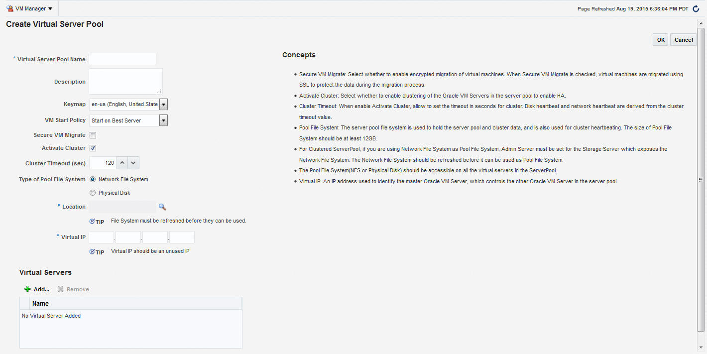
4.14 Creating a Virtual Server Pool
This section guides you through the ways of designing a server pool to meet your requirements.
Before creating a server pool, you need to consider how many physical servers will be contained in the server pool, and what functions each physical server will perform. The more virtual machines you will run in the server pool, the more resources these virtual machines will consume, therefore the more physical servers are needed to provide sufficient resources for the server pool.A server pool is scalable. If you find a server pool does not have sufficient resources, such as CPU and memory, to run the virtual machines and the applications inside, you can expand the server pool by adding more Oracle virtual servers.
A virtual server pool contains one or more virtual servers and guest virtual machines. A virtual server can belong to one and only one virtual server pool at a time. Guest virtual machines and resources are also associated with the server pools.
Prerequisites
-
A non-clustered virtual server pool can contain a maximum of 64 Oracle VM servers and a clustered virtual server pool can contain a maximum of 32 Oracle VM servers.
-
Virtual servers that can be deployed as the Master Server, the Utility Server, and/or the Guest Virtual Machine. At least one virtual server is required in a server pool.
-
All virtual servers in a server pool should have CPUs in the same CPU family. If they are not in the same CPU family, some operations such as live migration may fail. Though the CPUs should be in the same CPU family, they may have differing configurations, such as different number of cores. Other hardware components on the host computer may also differ, such as the amount of RAM, the number and size of disk drives, and so on.
Note:
Although the host computers may have differing configurations, Oracle recommends that all virtual servers in a server pool are identical.
-
A dedicated file system (either a NAS export, or a LUN) to use as the server pool file system is available.
-
IP addresses for the virtual servers must be available. The IP address to be used as the Master Server's virtual IP address must be an unused and available IP address.
-
To create a virtual server pool, you must be logged in as an Administrator with Add Any Target privilege.
-
To delete a virtual server pool, you must have Full privilege on the server pool and appropriate privileges on the virtual servers and guest virtual machines belonging to the virtual server pool.
4.14.1 Editing a Virtual Server Pool
You can edit the configuration information of a virtual server pool, including the description, key map, start policy, and so on. You can also change the master server, which controls the cluster, as well as whether the virtual machines are migrated securely. You cannot change the Virtual IP or the Pool File System used for the server pool. To edit a virtual server pool, follow these steps:
4.15 Creating a Zone
A zone is used to group related cloud resources together. Cloud zones can be created based on location, software lifecycle status, for grouping resources according to a cost center or for metering and chargeback purposes. Typically, a zone can cover a department or possibly a small data center. The cloud environment can comprise of one or more zones. Each zone has a set of metrics that show the aggregate utilization of the zone.
Prerequisites
-
To create a zone, you must be logged in as an Administrator with Add Any Target privilege.
-
To remove a zone, you must have Operator / Full privilege on the zone.
Follow these steps to create a zone:
4.16 Setting Up the Storage Quality of Service (QoS)
Storage QoS refers to quality of service that is defined at the storage server level. Setting up the storage QoS involves defining various storage properties. Before deploying a guest virtual machine, you can define the storage QoS, map this QoS to a storage server, and specify this QoS while deploying a guest virtual machine.
This involves defining the machine size, network type, and the storage QoS. After you have set up the storage QoS, you can set up the storage servers, network repositories, and storage arrays. This storage QoS can then be used during deployment of guest virtual machines.
4.16.1 Setting Up the Network Type
You can define the QoS for network by defining some network types like routable, internet-facing, and so on. After the network QoS has been defined, you can map this to any network that is being created. You can then use this network type while deploying a guest virtual machine.
To define the network QoS, follow these steps:
4.16.2 Setting Up the Machine Sizes
You can define the machine size that will be available to the SSA users and during deployment. To define the machine size, follow these steps:
- From the Enterprise menu, select Cloud, then select Oracle VM Infrastructure Home.
- Right click on the Infrastructure Cloud menu in the left panel and select Setup.
- Click the Machine Sizes link on the Infrastructure Cloud page.
- Click Add Machine Size.
- Enter the name (internal name of the machine size), description, number of VCPUs, amount of memory and local storage assigned to machines of this size. Click Save to add this machine size.
4.16.3 Configuring the Software Library User
While setting up the storage repository, you can import VM Templates, Assemblies, and other software components into the storage repository. To configure the software library user who has the privileges to perform these tasks, follow these steps:
- From the Enterprise menu, select Cloud, then select Oracle VM Infrastructure Home.
- Right click on the Infrastructure Cloud menu and select Setup.
- Click the Software Library User Configuration link on the Infrastructure Cloud page.
- Enter the password for the Cloud Software Library user who is allowed to import components from the Software Library. This password must be specified when the user accesses the Software Library and download the required components.
4.16.4 Configuring the Software Library User with External Management Agent
If the Management Agent is running on a remote machine, when importing the virtualization components, you must ensure that:
-
The Software Library user must have Execute command privileges on the remote host.
-
If Named Credentials are required to access the Management Agent on the remote host, the Software Library user must have View privileges while creating the Reference File locations for the Agent Storage Type.
To set up View privileges, follow these steps:
-
From the Setup menu, select Security, then select Named Credentials.
-
Select the Named Credentials to be used while creating the Software Library Reference Location of Storage Type: Agent.
-
Click Add Grant. Select the
CLOUD_SWLIB_USERand click Save.
To set up Execute privileges on the remote host, follow these steps:
- From the Setup menu, select Security, then select Administrators.
- Select the
CLOUD_SWLIB_USERand click Edit. - Navigate to the Target Privileges step. In the Target Privileges section, click Add and select the host target on which the Management Agent is running. The host target is added to the table.
- Select the host target added in the Step 3 and click the Edit icon in the Manage Privilege Grants column. Select Execute Command in addition to the already existing View option and click Continue.
- Click Save to save this configuration.
4.16.5 Defining the Request Purging Policy
All deployment requests can be retained for a certain period and then purged. To specify the number of days for which the requests should be available, follow these steps:
- From the Enterprise menu, select Cloud, then select Oracle VM Infrastructure Home.
- Right click on the Infrastructure Cloud menu and select Setup.
- Click the Request Archiving Policy link on the Infrastructure Cloud page.
- Select the Enable Archiving check box, specify the Archiving Duration, and click Apply. The requests will be archived for the specified period and will then be purged.
4.17 Patching the Oracle VM Server
Oracle provides a publicly available YUM repository which includes repositories for Oracle VM. These repositories include the full releases of Oracle VM and mirror those releases on the Oracle VM DVDs/ISOs. The Oracle VM Server must be patched to ensure that the latest software updates and enhancements are applied. Patching the Oracle VM Server involves the following:
-
Configuring the YUM Repository
-
Upgrading the Virtual Server
4.17.1 Configuring the YUM Repository
You can configure the YUM repository that is to be used to upgrade the virtual server. The configured YUM repository can be used for to upgrade all discovered virtual servers.
-
The YUM repository being configured must be present at a http location. You can configure an internal or public YUM repository.
To configure the YUM repository, follow these steps:
4.18 Acknowledging OVM Events
OVM events are generated for all operations performed on a server, server pool, storage, or network. The event can be Informational, Minor, or Critical. When a target is in an error state, a Critical event is generated. Targets with a Critical status cannot be used to perform any operations. The EM_CLOUD_ADMINISTRATOR can acknowledge such events as the associated targets cannot be used. To acknowledge an OVM event, follow these steps:
- From the Enterprise menu, select Cloud, then select Oracle VM Infrastructure Home.
- Click on a VM Server in the left panel to navigate to the VM Server Home page.
- From the VM Server menu, select OVM Events. The list of unacknowledged events appears. Select an event from the list and click Acknowledge to acknowledge the event.
4.19 Managing the NTP Configuration
Note:
-
This feature is available only with Oracle VM Manager 3.2.1 or later.
-
The NTP Server to be added must already be configured to provide the NTP service.
Network Time Protocol (NTP) is a networking protocol that enables clock synchronization across all Oracle VM Servers managed by an Oracle VM Manager. By default, when an Oracle VM Server is discovered, it is configured to use the Oracle VM Manager host computer as the NTP time source. You can configure a custom list of NTP servers that will be used to synchronize the clock when an Oracle VM Server is discovered. To create a custom list of NTP servers, follow these steps:
Note:
If multiple NTP configurations have been defined, the order in which have they have been defined will be used for clock synchronization.
4.20 Importing Virtual Machines
Note:
This feature is available only with Oracle VM Manager 3.2.1 or later.
You can import a virtual machine into Oracle VM Manager from an external location. The imported virtual machine is placed under the VM Zone, VM Server Pool, or the VM Server you have selected. The virtual machine must be located on an FTP or web server, either as separate files, or compressed into a single archive file (for example, a .tgz or .zip file).
To import a virtual machine, follow these steps:
4.21 Acknowledging the Repository Events
When the file system on the storage repository gets corrupted, a critical event is raised on the storage repository. This page displays all the critical events for the storage repository. To acknowledge repository events, follow these steps:
- From the Enterprise menu, select Cloud, then select Oracle VM Infrastructure Home. The Infrastructure Cloud Home page appears. Select an OVM Manager target from the left panel.
- From the VM Manager menu, select Administration, then select Storage Repository.
- A list of storage repositories that have been defined is displayed. Click on a storage repository name and click the Repository Events tab.
- A list of unacknowledged critical events is displayed. Select an event from list and click Acknowledge Events. The file system associated with the acknowledged event cannot be used
