| Oracle® Java ME Embedded Developer's Guide Release 8 E52611-01 |
|
 Previous |
 Next |
The I2C bus, often referred to as "i-2-c" or "i-squared-c", is a low-speed bus frequently used between micro-controllers and peripherals. I2C uses only two bi-directional lines, Serial Data Line (SDA) and Serial Clock (SCL), often pulled-up with resistors. Typical voltages used are +5 V or +3.3 V, although systems with other voltages are permitted.
When using the Raspberry Pi, be sure to check the manufacturer's specifications as to which voltages are acceptable for powering the peripheral. The Raspberry Pi provides both 3.3V and 5V pins.
To enable I2C on the Raspberry Pi, add the following lines to the /etc/modules files and reboot. Note that the file will need to be edited with root privileges.
    i2c-bcm2708
    i2c-dev
For this exercise, you will need the following hardware:
Table 6-1 Hardware for 7-Segment Display Example
| Hardware | Where to Obtain |
|---|---|
|
Raspberry Pi 512 MB Rev B |
Various third-party sellers |
|
Adafruit .56" 4-digit 7-segment display with HT16K33 I2C Backpack |
Adafuit or Amazon. Requires a small amount of soldering of the LED display unit to I2C logic board, as well as 4 I2C connector pins. |
|
Jumper Wires - Female to Female (x4) |
Electronics store. We used SchmartBoard P/N 920-0065-01 Rev A |
Our first example allows us to use the GPIO2 and GPIO3 pins for the I2C data and clock connections. Using these connections, we will write a simple program that allows us to set the display using an I2C connection.
In order to hook up the 7-Segment display to the Raspberry Pi properly, the jumper wires must be connected as shown in Table 6-2. Note that because there are only four connections, we opted not to use a T-cobber and a breadboard in this example.
Table 6-2 Raspberry Pi to HT16K33 Jumper Connections
| Pins on Raspberry Pi | HT16K33 Board |
|---|---|
|
5V (Pin 2) |
VCC |
|
Ground (Pin 6) |
GND |
|
GPIO 2 (Pin 3) |
SDA (Serial Data) |
|
GPIO 3 (Pin 5) |
SCL (Serial Clock) |
First, we need a basic class that communicates with the HT16K33 "LED backpack" that is soldered to the actual 7-segment LED display. Example 6-1 shows the source code for the 7-segment I2C display driver.
Example 6-1 HT16K33 I2C Driver for 7-Segment Display
import jdk.dio.DeviceManager;
import jdk.dio.i2cbus.I2CDevice;
import jdk.dio.i2cbus.I2CDeviceConfig;
import java.io.IOException;
import java.nio.ByteBuffer;
import java.util.logging.Level;
import java.util.logging.Logger;

public class LEDBackpack {

    I2CDeviceConfig LEDBackpackConfig;
    int[] displaybuffer = new int[10];

    byte[] OSCILLATOR_ON = {0x21};
    byte BRIGHTNESS = (byte) 0xE0;

    static byte HT16K33_BLINK_CMD = (byte) 0x80;
    static byte HT16K33_BLINK_DISPLAYON = (byte) 0x01;

    static byte HT16K33_BLINK_OFF = (byte) 0;
    static byte HT16K33_BLINK_2HZ = (byte) 1;
    static byte HT16K33_BLINK_1HZ = (byte) 2;
    static byte HT16K33_BLINK_HALFHZ = (byte) 3;

    static byte LETTER_J = 0x1E;
    static byte LETTER_A = 0x77;
    static byte LETTER_V = 0x3E;

    static final byte numbertable[] = {
        0x3F, /* 0 */
        0x06, /* 1 */
        0x5B, /* 2 */
        0x4F, /* 3 */
        0x66, /* 4 */
        0x6D, /* 5 */
        0x7D, /* 6 */
        0x07, /* 7 */
        0x7F, /* 8 */
        0x6F, /* 9 */
        0x77, /* a */
        0x7C, /* b */
        0x39, /* C */
        0x5E, /* d */
        0x79, /* E */
        0x71, /* F */};

    public LEDBackpack() {
        LEDBackpackConfig = new I2CDeviceConfig(1, 0x70, 7, 100000);
    }

    void begin() {

        try (I2CDevice slave = DeviceManager.open(LEDBackpackConfig)) {

            ByteBuffer oscOnCmd = ByteBuffer.wrap(OSCILLATOR_ON);
            slave.write(oscOnCmd);
            slave.close();

        } catch (IOException ioe) {
            Logger.getLogger(LEDBackpack.class.getName()).
            log(Level.SEVERE, null, ioe);
        }

        setBlinkRate(HT16K33_BLINK_OFF);
        setBrightness(15);

    }

    void setBrightness(int b) {

        if (b > 15) {
            b = 15;
        } else if (b < 0) {
            b = 0;
        }

        byte[] ea = {(byte) (BRIGHTNESS | b)};

        try (I2CDevice slave = DeviceManager.open(LEDBackpackConfig)) {

            ByteBuffer brightnessCmd = ByteBuffer.wrap(ea);
            slave.write(brightnessCmd);
            slave.close();

        } catch (IOException ioe) {
            Logger.getLogger(LEDBackpack.class.getName()).
                log(Level.SEVERE, null, ioe);
        }
    }

    void setBlinkRate(int b) {

        if (b > 3) {
            b = 0; // turn off if not sure
        } else if (b < 0) {
            b = 0;
        }

        byte[] ea =
            {(byte) (HT16K33_BLINK_CMD | HT16K33_BLINK_DISPLAYON | (b << 1))};

        try (I2CDevice slave = DeviceManager.open(LEDBackpackConfig)) {

            ByteBuffer blinkRateCmd = ByteBuffer.wrap(ea);
            slave.write(blinkRateCmd);
            slave.close();

        } catch (IOException ioe) {
            Logger.getLogger(LEDBackpack.class.getName()).
                log(Level.SEVERE, null, ioe);
        }
    }

    void writeDisplay() {

        try (I2CDevice slave = DeviceManager.open(LEDBackpackConfig)) {

            byte start[] = {0x00};

            ByteBuffer startCmd = ByteBuffer.wrap(start);
            slave.write(0x00, 1, startCmd);

            for (int i = 0; i < displaybuffer.length; i++) {

                byte b1a[] = {(byte) (displaybuffer[i] & 0xFF)};
                ByteBuffer b1Cmd = ByteBuffer.wrap(b1a);
                slave.write(i, 1, b1Cmd);

            }

            slave.close();

        } catch (IOException ioe) {
            Logger.getLogger(LEDBackpack.class.getName()).
                log(Level.SEVERE, null, ioe);
        }

    }

    void clear() {
        for (int i = 0; i < displaybuffer.length; i++) {
            displaybuffer[i] = 0;
        }
    }

}
This driver class contains five methods: begin(), setBrightness(), setBlinkRate(), writeDisplay(), and clear(). Let's cover each of these in more detail.
The begin() method will initialize the display. There are three operations that must be performed to do this properly. First, the oscillator on the HT16K33 LED backboard must be turned on. We can do this by sending a byte value of hex 0x21 across the bus. Next, we set the blink rate of the 7-segment display to one of four values: OFF, 2 Hz, 1 Hz, or .5 Hz. Finally, we can set the brightness of the display using a value of 1 to 15. For the latter two operations, we make use of the next two methods which can also be called independently.
The setBlinkRate() and setBrightness() methods simply take an input value, perform bounds checking, and calculate the correct byte value to send across the bus. Just like turning on the oscillator, we only need to send one byte across the bus to modify the blink rate or brightness to any level we choose.
The writeDisplay() method, on the other hand, is a little more complex. Here, the class makes use of an array of 10 integers, declared as a field, that serves as a display buffer. In reality, the writeDisplay() method will truncate any value larger then 255 before sending it across the bus, but making it an array of integers is helpful for the user.
Each of the entries in the array will map to an address on the HT16K33 "LED backpack" that can be written to using the I2C bus. The purpose of each of the addresses is shown in Table 6-3. Note that since the HT16K33 can drive different types of LED displays, several of the addresses are ignored when using this particular 4-character 7-segment display.
Table 6-3 HT16K33 7-Segment Display Addresses
| Address | Purpose |
|---|---|
|
0x00 |
7-Segment Display Character 1 and Period |
|
0x01 |
Ignored |
|
0x02 |
7-Segment Display Character 2 and Period |
|
0x03 |
Ignored |
|
0x04 |
Colon (0xFF for colon on; 0x00 for colon off) |
|
0x05 |
Ignored |
|
0x06 |
7-Segment Display Character 3 and Period |
|
0x07 |
Ignored |
|
0x08 |
7-Segment Display Character 4 and Period |
|
0x09 |
Ignored |
Each address can have one byte written to it. The contents of each byte is mapped out in binary as shown in Figure 6-1. As such, the number 7 with a decimal point is represented in binary as 10000111, which is equal to 0x87 in hexadecimal. Note that address 0x04 is reserved for the colon that appears between the first two numbers and the second two numbers in the display; it does not represent character 3.
Figure 6-1 Binary Encoding for 7-Segment Display

Example 6-2 shows a sample IMlet that will write the word "JAVA", without any decimal points or colon, to the display (even though the "V" looks the same as a "U" in the 7-segment display).
Example 6-2 IMlet to Write to the 7-Segment Display
import javax.microedition.midlet.MIDlet;

public class I2CExample1 extends MIDlet {

    public void startApp() {

        LEDBackpack backpack = new LEDBackpack();

        backpack.begin();
        backpack.setBrightness(10);
        backpack.setBlinkRate(LEDBackpack.HT16K33_BLINK_OFF);

        backpack.clear();
        backpack.writeDisplay();

        backpack.displaybuffer[0] = LEDBackpack.LETTER_J;
        backpack.displaybuffer[2] = LEDBackpack.LETTER_A;
        backpack.displaybuffer[4] = 0x00;                         //  No colon
        backpack.displaybuffer[6] = LEDBackpack.LETTER_V;
        backpack.displaybuffer[8] = LEDBackpack.LETTER_A;
        backpack.writeDisplay();

    }

    public void pauseApp() {
    }

    public void destroyApp(boolean unconditional) {
    }
}
The following permissions must be added to the Application Descriptor of the project so that it will execute without any security exceptions from the Oracle Java ME Embedded runtime.
Table 6-4 API Permissions for 7-Segment Display Project
| Permission | Device | Operation |
|---|---|---|
|
|
|
|
|
|
|
|
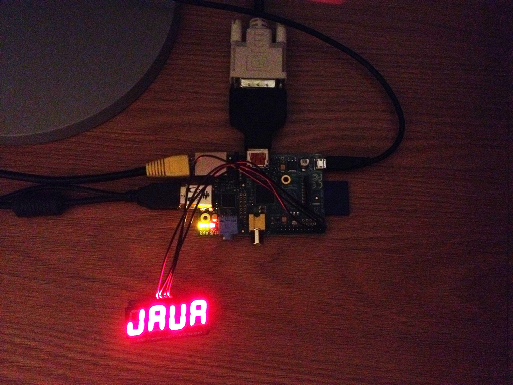
After running the application, you should see the display as shown in Figure 6-2.
Figure 6-2 Result of Running the 7-Segment Display IMlet

For this exercise, you will need the following hardware:
Table 6-5 Hardware for Example 2-2
| Hardware | Where to Obtain |
|---|---|
|
Raspberry Pi 512 MB Rev B |
Various third-party sellers |
|
16x2 LCD Display with an HD44780 Controller |
Amazon. Requires a small amount of soldering for the 16 connector pins that run on the top of the logic board. |
|
PCF8574N 8-bit I/O Expander Chip |
Mouser Electronics. |
|
T-Cobbler and Breadboard |
Electronics store. |
|
Jumper Wires |
Electronics store |
This example uses the I2C bus to interface to an LCD display with a Hitachi HD44780 backboard. The HD44780-based 16x2 character LCDs are inexpensive and widely available. However, in addition to the LCD display, we must also use a PCF8574-based IC, which is an general purpose bidirectional 8 bit I/O port expander that uses the I2C protocol.
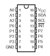
The first step is to hook up the Raspberry Pi to the PCF8574 chip. Typically, an IC chip is installed on a breadboard vertically along the center aisle, with the pins from the IC connecting to the holes adjacent to the center. The pinouts for the PCF8574N IC are shown in Figure 6-3.
Figure 6-3 Pinout Diagram for PCF8574N IC

Once the chip is on the breadboard, there are several pins on the chip that must be connected to the T-Cobbler using jumper wires, as shown in Table 6-6.
Table 6-6 Raspberry Pi to PCF8574N Jumper Connections
| Pins on T-Cobbler (Pi) | PCF8574N Pins |
|---|---|
|
+5V (Pin 2) |
VCC |
|
GND (Pin 6) |
GND |
|
SDA / GPIO 2 (Pin 3) |
SDA (Serial Data) |
|
SCL / GPIO 3 (Pin 5) |
SCL (Serial Clock) |
|
GND (Pin 6) |
A0 |
|
GND (Pin 6) |
A1 |
|
GND (Pin 6) |
A2 |
The first four pins shown in are the standard I2C connections that are required of any slave device that wishes to use the I2C bus. However, the remaining 3 pins are used to set the slave address on I2C bus #1, represented as a binary digit from 0-7 (A0=1, A1=2, A2=4) that is added to the hexidecimal value of 0x20. Because we are not running voltage on any of these pins, the address of the PCF8574N chip on the I2C bus should remain 0x20. If you'd like to verify this, login to the Raspberry Pi and issue the command shown in Figure 6-4. Here, the i2cdetect command shows that on bus 1 there is a device at address 0x20. To change the address, try connecting a 10K resistor between the 5V pin and one of the Ax pins and rerunning the command. The address that is reported should change accordingly.
The remaining pins P0-P7 and INT (high) on the PCF8574N are used to communicate with other devices, in this case the HD44780 chip that drives the 16x2 LCD display. Table 6-7 shows the connections to and from the PCF8574N chip and the HD44780 controller.
Table 6-7 Connections to PCF8574N and HD44780 Chip
| Raspberry Pi (T-Cobbler) | PCF8574N | HD44780 |
|---|---|---|
|
SCL / GPIO 3 (Pin 5) |
SCL |
|
|
SDA / GPIO 2 (Pin 3) |
SDA |
|
|
GND (Pin 6) |
A0 (see discussion on I2C address above) |
|
|
GND (Pin 6) |
A1 |
|
|
GND (Pin 6) |
A2 |
|
|
+5V (Pin 2) |
VDD |
|
|
GND (Pin 6) |
VSS |
|
|
P0 |
DB4 |
|
|
P1 |
DB5 |
|
|
P2 |
DB6 |
|
|
P3 |
DB7 |
|
|
P4 |
RS |
|
|
P5 |
R/W |
|
|
P6 |
E |
|
|
P7 (unused) |
||
|
INT (unused) |
||
|
+5V (Pin 2) |
VDD |
|
|
0 to +5V |
VO (variable resistor if desired for dimming backlit display) |
|
|
GND (Pin 6) |
VSS |
Before connecting the Px lines on the IC, try placing a resistor and an LED on a line coming from the P0 pin. Then, run the code shown in Example 6-3.
Example 6-3 Testing the PCF8574N I/O Expander Chip
import javax.microedition.midlet.MIDlet;
import jdk.dio.DeviceManager;
import jdk.dio.i2cbus.I2CDevice;
import jdk.dio.i2cbus.I2CDeviceConfig;
import java.io.IOException;

public class IOExpanderExample extends MIDlet {

    public void startApp() {

        LEDBackpackConfig = new I2CDeviceConfig(1, 0x20, 7, 100000);
        try (I2CDevice slave = DeviceManager.open(LEDBackpackConfig))
        {

            slave.write((byte)0x01);

        } catch (IOException ex) {
            //  Handle exception
        }

    }

    public void pauseApp() {

    }

    public void destroyApp(boolean unconditional) {

    }


}
To understand this example, it helps to look at the data line dialog, as shown in Figure 6-5. Each of the Px lines can be activated or deactivated by writing a binary number to the slave device, where P7 represents the most-significant digit and P0 represents the least-significant digit. Writing a value of 0x01 to the slave device will activate only the P0 line, which should in turn make the LED that is connected to it light up (be sure that the LED's cathode and anode connected are the right direction and that there is a resistor in line so the LED does not burn out!). Note that the LED will remain lit until a new value is written to the bus, or the PCF8574N chip loses power.
Figure 6-5 I/O Data Bus with the PCF8574N chip

Next, complete the circuit according to Table 6-7. Example 6-4 shows a sample driver class that will control the HD44780.
Example 6-4 LCD Driver Class to Control the HD44780 Chip
import javax.microedition.midlet.MIDlet;
import jdk.dio.DeviceManager;
import jdk.dio.i2cbus.I2CDevice;
import jdk.dio.i2cbus.I2CDeviceConfig;
import java.io.IOException;
import java.util.logging.Level;
import java.util.logging.Logger;

public class LCDDisplay {

    I2CDeviceConfig LEDBackpackConfig;
    I2CDevice slave;

    public LCDDisplay()
            throws InterruptedException, IOException {

        LEDBackpackConfig = new I2CDeviceConfig(1, 0x20, 7, 100000);
        slave = DeviceManager.open(LEDBackpackConfig);

    }

    public void begin()
            throws InterruptedException, IOException {

        slave.write(0x03);
        byte result1 = (byte) slave.read();
        Thread.sleep(5);

        slave.write(0x03);
        byte result2 = (byte) slave.read();

        Thread.sleep(1);
        slave.write(0x03);
        byte result3 = (byte) slave.read();

        Thread.sleep(1);

        slave.write(0x02);
        byte result4 = (byte) slave.read();

        writeCommand((byte) 0x28);
        writeCommand((byte) 0x08);
        writeCommand((byte) 0x01);
        writeCommand((byte) 0x06);
        writeCommand((byte) 0x0C);

        Thread.sleep(1);
        byte result5 = (byte) slave.read();

    }

    public void writeCharacter(byte charvalue)
            throws InterruptedException, IOException {

        slave.write((byte) (0x10 | (charvalue >> 4)));
        strobe();
        slave.write((byte) (0x10 | (charvalue & 0x0F)));
        strobe();
        slave.write(0x00);
        Thread.sleep(1);

    }

    public void writeCommand(byte value)
            throws InterruptedException, IOException {

        slave.write((byte) (value >> 4));
        strobe();
        slave.write((byte) (value & 0x0F));
        strobe();
        slave.write(0x00);
        Thread.sleep(5);

    }

    public void writeString(int line, String string)
            throws InterruptedException, IOException {

        if (line == 1) {
            writeCommand((byte) 0x80);
        } else if (line == 2) {
            writeCommand((byte) 0xC0);
        } else if (line == 3) {
            writeCommand((byte) 0x94);
        } else if (line == 4) {
            writeCommand((byte) 0xD4);
        }

        char[] chars = string.toCharArray();

        for (int i = 0; i < chars.length; i++) {
            writeCharacter((byte) chars[i]);
        }
    }

    public void strobe()
            throws InterruptedException, IOException {

        Thread.sleep(1);

        byte readResult = (byte) slave.read();
        readResult |= 0x40;
        slave.write(readResult);

        Thread.sleep(1);

        readResult = (byte) slave.read();
        readResult &= 0xBF;
        slave.write(readResult);

    }

    public void clear()
            throws InterruptedException, IOException {

        Thread.sleep(5);

        writeCommand((byte) 0x01);
        Thread.sleep(5);

        writeCommand((byte) 0x02);
        Thread.sleep(5);

    }

    public void end()
            throws IOException {

        slave.close();

    }

}
To use the driver class, run the IMlet shown in Example 6-5.
Example 6-5 IMlet to Write to the 16x2 LCD Display
import java.io.IOException;
import javax.microedition.midlet.MIDlet;

public class I2CExample2 extends MIDlet {

    public void startApp() {

        LCDDisplay display;
        try {
            display = new LCDDisplay();
            display.begin();
            display.clear();
            display.writeString(1, "Java ME");
            display.writeString(2, "Embedded");
            display.end();
        } catch (InterruptedException ex) {
            ex.printStackTrace();
        } catch (IOException ex) {
            ex.printStackTrace();
        }

    }

    public void pauseApp() {
    }

    public void destroyApp(boolean unconditional) {
    }
}
The following permissions must be added to the Application Descriptor of the project so that it will execute without any security exceptions from the Oracle Java ME Embedded runtime.
Table 6-8 API Permissions for LCD Example
| Permission | Device | Operation |
|---|---|---|
|
|
|
|
|
|
|
|
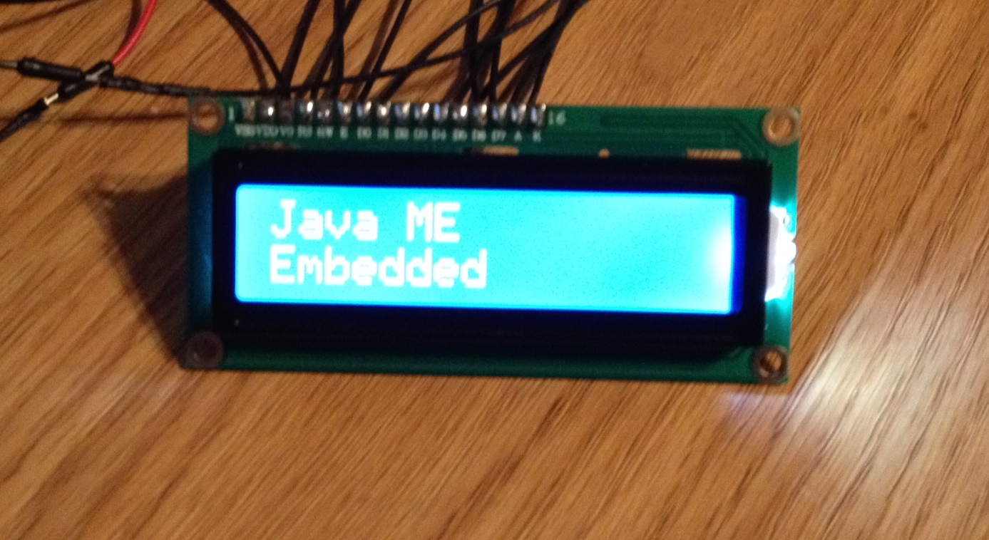
After running the application, you should see the display as shown in Figure 6-6.
Figure 6-6 LCD Display after Running Example
