| Oracle® Java ME Embedded Developer's Guide Release 8 E52611-01 |
|
 Previous |
 Next |
The Serial Peripheral Interface or SPI bus is a synchronous serial data link that operates in full duplex mode. In other words, data can be sent and received at the same time. Devices communicate in master/slave mode, where the master device initiates the data exchange with one or more slaves. Multiple slave devices are allowed with individual slave select lines.
The SPI bus specifies four logic signals:
SCLK : Serial Clock (a clock signal that is sent from the master).
MOSI : Master Output, Slave Input (data sent from the master to the slave).
MISO : Master Input, Slave Output (data sent from the slave to the master).
SS : Slave Select (sent from the master, active on low signal). Often paired with the Chip Select (CS) line on an integrated circuit that supports SPI.
In order to enable the SPI bus on the Raspberry Pi, uncomment the entry spi_bcm2708 in the file /etc/modprobe.d/raspi-blacklist.conf. Note that you will need to have root privileges to edit the file.
Because the Raspberry Pi board does not come with a analog-to-digital converter, the SPI bus can be used to communicate with a peripheral analog-to-digital converter chip that is reading an analog signal.
For this exercise, you will need the following hardware:
Table 7-1 Hardware for Example 3-1
| Hardware | Where to Obtain |
|---|---|
|
Raspberry Pi 512 MB Rev B |
Various third-party sellers |
|
Texas Instruments TLC549CP 8-bit ADC |
Various electronics suppliers. We used mouser.com. |
|
T-Cobbler and Breadboard |
Adafuit. See Chapter 1 for more information. |
|
Potentiometer |
Electronics store |
|
Jumper Wires (M/M and F/F) |
Electronics store. |
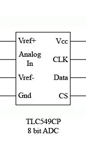
The data sheet of the TLC549CP shows 8 pins, as shown in Figure 7-1. Note that the SPI connections reside on the right side of the chip, while the connections for measuring the analog signal are on the left side of the chip.
Figure 7-1 Pinouts for TLC549CP Analog-to-Digital Converter Chip

In order to connect the TLC549CP chip to the Raspberry Pi, the SPI connections must be connected as shown in Table 7-2.
Table 7-2 Raspberry Pi to TLC549CP SPI Pins
| Pins on Raspberry Pi | TLC549CP ADC Board Pins (Right Side) |
|---|---|
|
3.3V |
VCC |
|
SCLK (GPIO 11 / Pin 23) |
CLK |
|
MISO (GPIO 9/ Pin 21) |
Data |
|
CE0 (GPIO 8 / Pin 24) |
CS |
The other four pins must be connected to provide the analog voltage to measure. In this example, we are using a potentiometer (in effect, a variable resistor) to vary the amount of voltage being sent into the Analog In pin.
Table 7-3 shows how to connect the remaining pins on the TCL549CP chip.
Table 7-3 TLC549CP to Analog Signal Pins
| TLC549CP ADC Board Pins (Left Side) | Analog Signal |
|---|---|
|
Vref+ |
Voltage (Side Pin on Potentiometer) / 3.3V |
|
Analog In |
Variable Voltage Signal (Middle Pin on Potentiometer) |
|
Vref- |
Voltage (Other Side Pin on Potentiometer) |
|
GND |
To Ground |
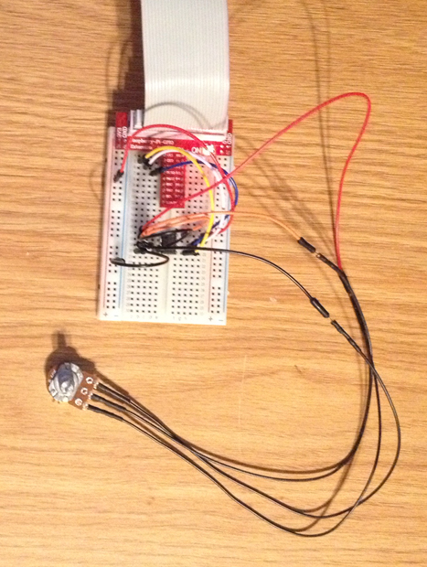
Note that in order to complete our circuit and provide power to the potentiometer, the Vref+ must be also connected to a 3.3V input, and the Vref- must be connected to a ground. The chip does not provide voltage. You can test the voltage that is being sent through the potentiometer with a voltmeter to ensure that the circuit is working properly. The completed circuit on the breadboard is shown in Figure 7-2.
Figure 7-2 Breadboard with the Analog-to-Digital Converter Circuit

Once this is completed, we can use the source code in Example 7-1 to test out the ADC chip.
Example 7-1 Testing Out the SPI Bus Connection
import jdk.dio.Device;
import jdk.dio.DeviceManager;
import jdk.dio.spibus.SPIDevice;
import jdk.dio.spibus.SPIDeviceConfig;
import java.io.IOException;
import java.nio.ByteBuffer;
import java.util.logging.Level;
import java.util.logging.Logger;
import javax.microedition.midlet.MIDlet;


public class SPIExample1 extends MIDlet {

    public void startApp() {

        System.out.println("Preparing to open SPI device...");

        SPIDeviceConfig config = new SPIDeviceConfig(0, 0,
                SPIDeviceConfig.CS_ACTIVE_LOW,
                500000,
                3,
                8,
                Peripheral.BIG_ENDIAN);

        try (SPIDevice slave = (SPIDevice)DeviceManager.open(config)) {

            System.out.println("SPI device opened.");

            for (int i = 1; i < 200; i++) {
                ByteBuffer sndBuf = ByteBuffer.wrap(new byte[]{0x00});
                ByteBuffer rcvBuf = ByteBuffer.wrap(new byte[1]);
                slave.writeAndRead(sndBuf,rcvBuf);
                System.out.println("Analog to digital conversion at " +
                    i + " is: " + rcvBuf.get(0));
                Thread.sleep(1000);

            }

        } catch (IOException ioe) {
            // handle exception
        } catch (InterruptedException ex) {
            Logger.getLogger(SPIExample1.class.getName()).
                log(Level.SEVERE, null, ex);
        }

    }

    public void pauseApp() {
    }

    public void destroyApp(boolean unconditional) {
    }
}
This program is very simple: it opens up a connection to the Raspbeery Pi SPI bus using a SPIDeviceConfig and writes a byte to the peripheral device: the ADC chip. Since there is no input connection being sent from the master (the Raspberry Pi) to the slave (the ADC chip), this data is effectively ignored. The SPI bus will, concurrently, attempt to retrieve a byte of data from the chip. This byte is passed along the MISO line, which returns an 8-bit number that represents the current voltage level. This process will be repeated 200 times, with a one-second delay between each sampling on the bus.
The program output looks like the following. As the program is running, try turning the dial on the potentiometer to vary the voltage that is being sent into the chip. Here, we are turning the voltage from higher to lower, and the ADC chip is representing this with a steady drop in the 8-bit value that is returned.
Starting emulator in execution mode
...
About the open device
Device opened...
Value for 1 is: 145
Value for 2 is: 143
Value for 3 is: 120
Value for 4 is: 113
Value for 5 is: 90
Value for 6 is: 75
Value for 7 is: 63