| Oracle® Java ME Embedded Getting Started Guide for the Windows Platform Release 8 EA 2 for NetBeans on Windows E48511-01 |
|
 Previous |
 Next |
| Oracle® Java ME Embedded Getting Started Guide for the Windows Platform Release 8 EA 2 for NetBeans on Windows E48511-01 |
|
 Previous |
 Next |
Beta Draft: 2014-02-15
The Oracle Java ME SDK 8 EA 2 External Events Generator allows you to test the capabilities of your device by simulating events on that device. For example, you can send pulses to a pulse counter.
The External Events Generator is started by clicking on the External Events Generator icon, as shown in Figure 4-1, or by selecting Tools --> External Events Generator.
Figure 4-1 External Events Generator Icon
Although the External Events Generator functionality is largely the same for both the EmbeddedDevice1 and Qualcomm_IoE_Device emulators, they are not exactly the same. This section describes the tabs and features for the EmbeddedDevice1 External Events Generator.
When the External Events Generator is started the default tab is the Audio-to-Digital Converter (ADC) tab, as shown in Figure 4-2.
The External Events Generator has the following tabs:
ADC. The Analog-to-Digital Conversion tab allows you to test analog audio input.
GPIO. This General Purpose Input Output (GPIO) option.
By default, this tab displays ports and pins for a specific device. You can create a custom device to represent a different GPIO device.
See the Device Access API (installdir\docs\api\deviceaccess.zip) for a description of the GPIO interface.
Location. Allows you to set and test the location functionality of the device.
MMIO. The memory-mapped I/O (MMIO) option is visible only for the EmbeddedDevice1 emulator. If not already selected, select the following default device:
BIG_ENDIAN_DEVICE. A Big Endian device that contains all block types: byte, short, int, and block.
|
Note: If you are using a custom device created with the Custom Device Editor, the MMIO device list might include additional devices. For more information on the Custom Device Editor, see Chapter 5, "Working With Devices" |
See the Device Access API (installdir\docs\api\deviceaccess.zip) and the Embedded Support API (installdir\docs\api\embedded-support-api.zip) for descriptions of the MMIO interface.
Mobile. Allows you to set the unique International Mobile Subscriber Identity (IMSI) and the International Mobile Station Equipment identity (IMEI) identifiers of the device.
Power Management. This tab allows you to emulate the battery life of an external device, in seconds.
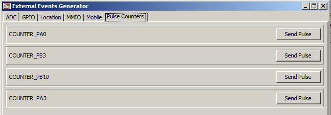
Pulse Counter. This tab displays the current pulse counters on the device. The default configurations are:
COUNTER_PA0
COUNTER_PB3
COUNTER_PB10
COUNTER_PA3
You can configure the pulse counters you want and send a signal to the configured pulse counter by clicking Send Pulse.
The Analog-to-Digital Converter (ADC) tab allows you to test analog input of ADC channels, as shown in Figure 4-3, including Channel, DAC Input, and minimum and maximum values. You can use the slider to set input voltage manually or connect selected DAC output to selected ADC input.
Figure 4-3 The External Events Generator ADC Tab

To generate input events for General Purpose I/O, select the GPIO tab. Here, you can toggle the value of each of the pins from high to low and use a wave generator to simulate a more complex signal to the emulator. The External Events Generator GPIO tab is shown in Figure 4-4.
Figure 4-4 The External Events Generator GPIO Tab
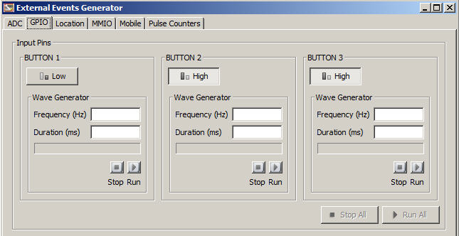
To toggle a Button value between Low and High, click on the Button.
When a button value has been changed on the External Events Generator GPIO tab, you see a corresponding change to the Value field of the GPIO Pins tab for the EmbeddedDevice1 emulator, as shown in Figure 4-5.
Figure 4-5 The Button Fields of the EmbeddedDevice1 Emulator GPIO Pins Tab

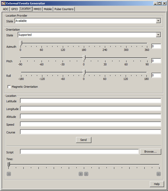
The Location tab of the External Events Generator allows you to test the Location functionality of your device, as shown in Figure 4-6.
The Location tab has the following fields:
Location Provider. Indicates if the Location Provider is available, temporarily unavailable, or out of service.
Orientation. Indicates if the Orientation is supported, unsupported, or unavailable. Also allows you to set the Azimuth, Pitch, Roll, and Magnetic Orientation of your device.
Location. Allows you to specify specific emulation settings for your device, such as Latitude, Longitude, Altitude, Speed, and Course. It also allows you to browse for and run a specified script or demo program to test the Location capabilities of your device. For a specified script, you can set the duration of the run using the Time slider.
Figure 4-6 The External Events Generator Location Tab
The Memory Mapped I/O tab of the External Events Generator allows the user to simulate sending input event IDs to different MMIO devices that support events. Currently, only the BIG_ENDIAN_DEVICE supports events. The MMIO tab is shown in Figure 4-7.
Figure 4-7 The External Events Generator MMIO Tab

|
Note: The External Events Generator Mobile tab is not used by embedded applications, so it is not documented here. |
The Power Management tab allows you to define power settings for a device battery or external device. The Power Management tab is shown in Figure 4-8.
The Pulse Counter tab allows you to send a sequence of pulses to the pulse counters available in the current embedded devices, as shown in Figure 4-9.
Figure 4-9 The External Events Generator Pulse Counters Tab
The tabs on the External Events Generator for the Qualcomm_IoE_Device emulator largely match those of the EmbeddedDevice1 emulator. Those that differ are shown below.
The GPIO tab for the Qualcomm_IoE_Device External Events Generator is similar in function to the GPIO tab in the EmbeddedDevice1 emulator, but has many more buttons available, as shown in Figure 4-10.
Figure 4-10 The Qualcomm_IoE_Device External Events Generator GPIO Tab
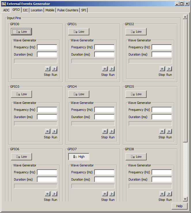
To toggle a Button value between Low and High, click on the Button.
When a button value has been changed on the External Events Generator GPIO tab, you see a corresponding change to the Value field of the GPIO Pins tab for the Qualcomm_IoE_Device emulator, as shown in Figure 4-11.
Figure 4-11 The GPIO Pins Tab of the Qualcomm_IoE_Device Emulator

The Inter-Integrated Circuit (I2C) tab displays information for a selected slave device, and data sent to and received from a master device.
The three sample sensors in the I2C tab are:
G-Sensor. Operates in the same way as described in the External Events Generator SPI tab. However, the sample IMLet reads the accelerometer values through the I2C interface. For more information, see "The Serial Peripheral Interface (SPI) Tab."
Light Sensor. Allows the user to test three kinds of light sensing: ambient light, proximity, and Infrared (IR). A lux value can be specified, and the values changed within the lux value range by moving the Light slider.
Temperature Sensor. High and Low temperature values can be set, and temperature values read when the slider is moved.
The Qualcomm_IoE_Device emulator External Events Generator I2C tab is shown in Figure 4-12.
Figure 4-12 The Qualcomm_IoE_Device External Events Generator I2C Tab
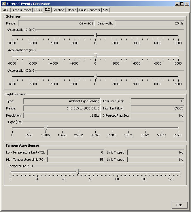
The Light Sensor has the following fields:
Type. Ambient Light. Allows changes in light brightness to be registered by the emulated sensor.
Low Limit (lux). The low limit value is 0 lux.
Range. The range is 1 (defined as 0.015 lux to 1000.0 lux)
High Limit (lux). The high limit value is 65535 lux.
Resolution. Allows 16 bits.
Interrupt Flag Set. When sensor values stay within the defined range, the value of the Interrupt Flag is No.
Light (lux). Allows the user to define the lux value for the application by moving the slider. The range values allowed are 0 lux at the low end and 65535 lux at the high end.
The Pulse Counters tab of the Qualcomm_IoE_Device External Events Generator works the same as the tab in the External Events Generator for the EmbeddedDevice1. However, in the Qualcomm_IoE_Device tab there is only one counter, as shown in Figure 4-13.
Figure 4-13 The Qualcomm_IoE_Device External Events Generator Pulse Counters Tab

The Qualcomm_IoE_Device emulator External Events Generator SPI tab provides a sample accelerometer sensor, G-Sensor, as shown in Figure 4-14.
Figure 4-14 The Qualcomm_IoE_Device External Events Generator SPI Tab
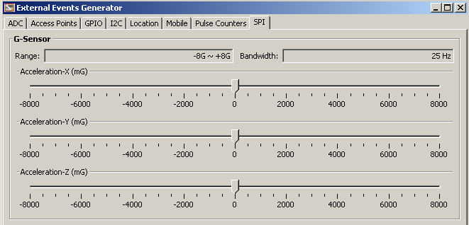
The G-Sensor sample allows an IMlet to read accelerometer values from the emulator through the Serial Peripheral Interface. Move the slider of the X, Y, and Z acceleration scale to change the x, y, and z values transmitted over SPI. The minimum and maximum values for the sliders in the G-Sensor are defined by the Java ME application.
The G-Sensor sample duplicates in emulation the functionality of the digital, triaxial acceleration sensor on the Qualcomm Orion IoE embedded device. The acceleration sensor is used to sense tilt, motion, and shock vibration in embedded devices, such as medical instruments, computer peripherals, and monitoring devices.
The G-Sensor has the following fields:
Range. Allows between -8G and +8G.
Bandwidth. Allows 25 Hz.
Accelerator-X. Allows you to select a value within a specified range by moving the slider position.
Accelerator-Y. Allows you to select a value within a specified range by moving the slider position.
Accelerator-Z. Allows you to select a value within a specified range by moving the slider position.
For more information on working with the Qualcomm Orion IoE embedded device, see the Oracle Java ME Embedded Getting Started Guide for the Reference Platform (Qualcomm Orion IoE).