| Oracle® Java ME Embedded Getting Started Guide for the Windows Platform Release 8 EA 2 for NetBeans on Windows E48511-01 |
|
 Previous |
 Next |
| Oracle® Java ME Embedded Getting Started Guide for the Windows Platform Release 8 EA 2 for NetBeans on Windows E48511-01 |
|
 Previous |
 Next |
Beta Draft: 2014-02-15
The Oracle Java ME SDK 8 EA 2 embedded emulation environment provides you with a platform for testing and running Oracle Java ME Embedded Profile (MEEP) IMlet suites without having to install those IMlet suites onto an embedded device.
This is done using two default embedded emulators (EmbeddedDevice1 and EmbeddedDevice2). These emulators do not represent a specific device, but provide a correct implementation of the APIs for this platform.
The Qualcomm_IoE_Device emulator, which is also described in this chapter, provides an emulation of the Qualcomm Orion IoE embedded hardware device. For more information, see the Oracle Java ME Embedded Getting Started Guide for the Reference Platform (Qualcomm Orion IoE).
This chapter describes how to run and use the Oracle Java ME SDK 8 EA 2 embedded emulators.
If the Embedded emulator is not displayed when you finish building the sample project described in Chapter 2, it can be launched from the Windows command line. For more information, see Appendix A, "Using the Command Line Emulator."
The Oracle Java ME SDK 8 EA 2 Embedded emulator provides several ways to interact with an emulated device (for example, EmbeddedDevice1), as shown in Figure 3-1.
The Application menu (and associated icons) allow you to install and run IMlet suites.
The Tools menu allows you to manage a Landmark Store or file system.
The External Events Generator icon (and Tools menu option) allows you to configure pins, ports, interfaces, and other customizable parts.
The View menu allows you to display log information and other output in a console window.
The Help menu allows you to display context-sensitive help to get more information about the emulator screen and functions.
Figure 3-1 The Oracle Java ME SDK 8.0 EA Emulator Toolbar and Menu Items
When the Oracle Java ME SDK 8 EA 2 emulator starts, it appears with the Application Management System (AMS) tab selected as the default, as shown in Figure 3-2.
Figure 3-2 The Oracle Java ME SDK 8 EA 2 Emulator (AMS Tab) Default Screen
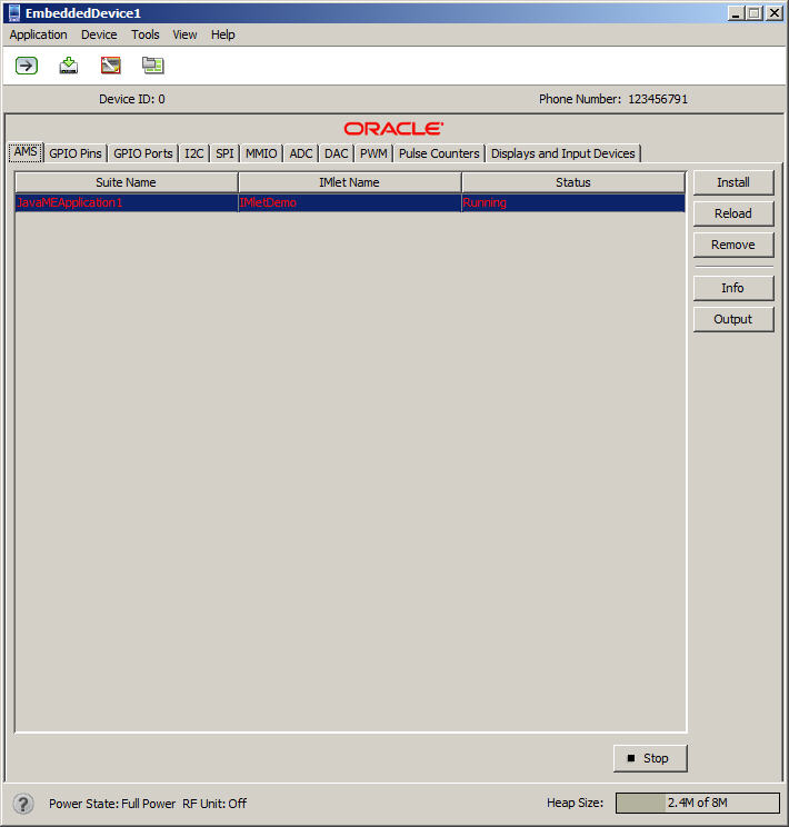
Device Name. Shown in the upper left window frame.
Menus. The Menus available on the Oracle Java ME SDK 8 EA 2 emulators are:
Application - Allows you to install and run IMlet suites.
Device - Allows you to observe Wireless Messaging (WMA) messages addressed to the device.
Tools - Allows you to manage access points, landmarks, the file system, launch the External Events Generator.
View - Allows you to view output from a running application, logging information from the emulator, and to define desktop and exit behavior.
Help - Allows you to find context-specific emulator information.
Toolbar. The Toolbar provides shortcuts for the following operations:
Run IMlet Suite
Install IMlet Suite
Launch the External Events Generator
Emulator window always on top
|
Note: When the Device Manager detects an external embedded device, only the Application, View, and Help menus and the Run IMlet Suite, Install IMlet Suite, and Emulator window always on top icons in the Toolbar are available in the device display. |
Device ID. Numerical identifier that is unique for each device.
Phone Number. A number used by the emulator to send messages to itself for testing purposes.
Display Panel and Tabs. The display panel displays fields and information dependent on the selected tab:
AMS. The AMS (Application Management System) tab displays the name of an IMlet suite, the IMlet, and the status of the IMlet suite, for all installed IMlet suites. You can select a suite and perform one of the following operations by clicking the corresponding button to the right of the display:
Install - Specify the location of the IMlet suite path or URL and the security domain and click OK to load the IMlet suite.
Reload - Reload the application.
Remove - Remove the application.
Info - Provides information about the IMlet suite.
Output - Opens a dialog box displaying output information about the application
GPIO Pins. The General Purpose Input Output (GPIO) Pins tab displays which pins are selected to output and their high or low values.
GPIO Ports. The GPIO Ports tab displays a list of ports, which ports are selected to output, and their maximum and current values.
I2C. The Inter-Integrated Circuit (I2C) tab displays information for the selected slave device and data sent to a master device and data received from a master device.
SPI. In the default SPI implementation, buffered written data can be read from the Slave named SPI. If you have created a custom implementation with the Custom Device Editor, the Slave drop down list might have additional slaves.
MMIO. The memory-mapped I/O tab displays information for the current device.
ADC. The Analog-to-Digital Converter tab displays the current channel, converter number, sampling intervals, minimum and maximum values, and other information.
DAC. The Digital-to-Analog Converter tab displays the current channel information, converter characteristics, and a graphic display of signal characteristics with the x-axis showing the digital input and the y-axis showing the analog output.
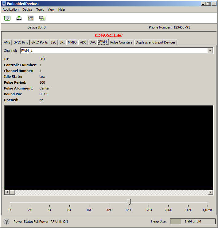
PWM. The Pulse Width Modulation tab displays the amount of electrical power flowing to a device.
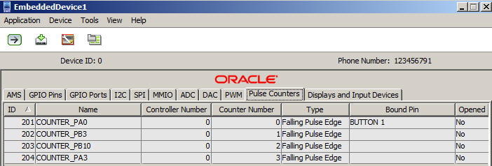
Pulse Counters. The Pulse Counters tab displays the ID, counter name, counter number, counter type, and the pins to which the counters are bound.
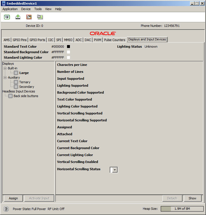
Displays and Input Devices. The Displays and Input Devices tab displays color and other settings for an emulated device.
Emulator Status Bar. Information about the current system state is shown in the status bar at the bottom of the emulator window. Also shown is the memory indicator showing used and total memory.
Run/Stop Button. A toggle button that can be used to start and stop an IMlet suite.
The first tab in the emulator, the AMS tab, displays which Oracle Java ME SDK 8 EA 2 applications are installed, running, or stopped.
You can use the buttons in the AMS tab, as shown in Figure 3-3, to do the following:
Install or Reload an application
Remove an application
Display Info about an application
Display Output about an application in a separately-displayed Output Console
The Output Console window of the AMS tab allows you to display logging information about a selected application, as shown in Figure 3-4.
Output Console information can be Error output, Standard output, or All output. The selected output can be saved to a file in your file system by selecting the Save button.
The GPIO tab lists the emulator's current General Purpose I/O (GPIO) pins and their directional state (output). For GPIO pins, the current value is shown as low or high. The GPIO Pins tab is shown in Figure 3-5.
For GPIO ports, the port ID and port Name is shown, along with the port's Maximum Value and current Value. If you select the line that displays the available ports, it displays the pins bound to that specific port, as shown in Figure 3-6.
Selecting the line that displays the available ports shows the pins bound to that port, as shown in Figure 3-7.
The Inter-Integrated Circuit (I2C) tab emulates a simple peripheral slave device that echoes back any data that is sent to it. Both the sent and received data are shown in their appropriate window panes, as shown in Figure 3-8.
The Serial Peripheral Interface (SPI) tab is similar to the I2C tab. It emulates a simple peripheral slave device that echoes back any data that is sent to it. Both the sent and received data are shown in their appropriate tabs, as shown in Figure 3-9.
The MMIO tab emulates the Memory-Mapped I/O (MMIO) interface bus. It displays an information table about the selected device, as shown in Figure 3-10.
The Analog-to-Digital Converter (ADC) tab displays current Channel information, such as ID, Converter Number, Minimum and Maximum Values, Sampling Intervals, and more, as shown in Figure 3-11.
The Digital-to-Analog Converter (DAC) tab displays current Channel information, such as Minimum and Maximum Values, Sampling Interval, Reference Voltage, and more, as shown in Figure 3-12.
The Pulse Width Modulation (PWM) tab allows you to monitor a signal (pulse) that can be encoded for a specific width (duration). It displays information about a specific pulse counter, such as its configuration and current state, as shown in Figure 3-13.
To encode and send a pulse of a specific duration, use the PWM tab of the External Events Generator. For more information, see Chapter 4.
Figure 3-13 The Pulse Width Modulation Tab
The Pulse Counters tab allows you to send pulse information to as many as four counters. as shown in Figure 3-14. There are four kinds of pulses:
Falling Pulse Edge - Can only be bound to input pins with the Falling Edge trigger.
Rising Pulse Edge - Can only be bound to input pins with the Rising Edge trigger.
Negative Pulse Edge - Can only be bound to input pins with the Both Edges trigger.
Positive Pulse Edge - Can only be bound to input pins with the Both Edges trigger.
Figure 3-14 The Emulator Pulse Counters Tab
The Displays and Input Devices tab allows you to gather information about specific displays attached to your device. This includes both primary and auxiliary displays. This tab also displays information about any input devices, such as a Qualcomm Orion IoE or Raspberry Pi embedded platform, as shown in Figure 3-15.
Figure 3-15 The Displays and Input Devices Tab
The menus on the Oracle Java ME SDK 8 EA 2 emulator allow you to do a number of operations, including running and installing IMlet suites, managing landmarks, file systems, and access points, and running the External Events Generator.
The Application menu lets you install and run IMlet suites.
To install an IMlet suite, select Application > Install IMlet Suite.
This displays the Install IMlet Suite box, as shown in Figure 3-16. Click OK.
To run an IMlet suite, select Application > Run IMlet Suite.
This displays the Run IMlet Suite box, as shown in Figure 3-17. Enter the path or URL for the IMlet suite and click OK.
Exit. Shuts down the emulator process and quits.
The Device menu allows you to see messages in the Messages box that are directed at the currently-running emulator from other devices. Messages provide information such as the timestamp, subject, encoding, and other information, as shown in Figure 3-18.
Select Device > Messages to see what is written in the message area. Messages are sent to a device in the following cases:
An SMS message is sent without a port in the address (or the port number is 0)
An SMS text message is sent with a port in the address, but there is not a Java ME application listening on the specified port
To test sending messages to the device use the WMA Console in NetBeans 8.0 Beta, or from the command line, use wma-tool.exe to send SMS messages.
The Tools menu allows you to manage landmarks, file systems, and access points. It also provides another way to launch the External Events Generator.
Manage Landmarks. Landmarks are used to emulate location information for an embedded device.
You can use the default Landmark store, create new landmark stores, define landmark categories, and carry out other landmark operations, as shown in Figure 3-19.
Manage File System. Managing a file system allows you to mount a file tree to your emulation environment, providing access to components not installed in your immediate location.
Once a file tree is mounted, it can also be unmounted, as shown in Figure 3-20.
Connectivity. Setting Connectivity allows you to define the network connectivity for your embedded emulation environment.
As shown in Figure 3-21, four tabs are available on the Connectivity screen:
Access Points. Allows you to add and remove access points, and characteristics of a specific access point, such as the bearer type, network interface, and the service set ID (SSID).
Network Interfaces. Allows you to add and remove network interfaces, and define characteristics of a specific network interface, such as the type, timeout interval, and connection interface device.
Cellular Network. Allows you to add and remove a cellular network, and define characteristics for a specific cellular network, such as CDMA or 3GPP, connection protocol, and other details.
Subscribers. Allows you to add or remove a subscriber, and define characteristics for a subscribers, such as phone number, network type, international mobile subscriber identity (IMSI), and other details.
External Events Generator. For more information on the External Events Generator, see Chapter 4, "Using the External Events Generator"
The View menu allows you to view output in a device log or output console, to set your Embedded emulator so it always appears on top on your desktop, and show additional information on exit.
Output Console.... Allows you to see output from an application running in the emulator, as shown in Figure 3-22. You have three choices for filtering output: All, Standard Output, and Error Output.
You can save system output information to a text file by clicking Save in the output window.
Device Log. Allows you to display logging info, as shown in Figure 3-23. You have several levels of logging to choose from, including Trace, Debug, info, Warn, Error, and Fatal.
You can save log information to a text file by clicking Save in the output window.
Always on Top. Allows you to keep the emulator on top of other windows open on your desktop.
Show Hot Deployment Hint on Exit. Upon exit from the emulator, provides suggestions on how to save your work and easily restart the emulator.
The Oracle Java ME SDK 8 EA 2 runs applications on an emulator or an external device.
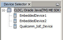
The Device Connections Manager automatically starts detecting devices when Oracle Java ME SDK 8 EA 2 is installed. The default emulators are automatically found and displayed in the NetBeans 8.0 Beta Device Selector window (Tools > Java ME > Device Selector), as shown in Figure 3-24.
Figure 3-24 Available Devices in the NetBeans 8.0 Beta Device Selector
The Device Selector can also be launched from the Windows command line. Enter the following:
C:\>Java_ME_platform_SDK_8.0_EA\bin\device-selector.exe
This displays the standalone Device Selector, as shown in Figure 3-25.
Figure 3-25 The Standalone Device Selector

Typically an emulator is launched when a Oracle Java ME SDK 8 EA 2 project is run from the NetBeans 8.0 Beta IDE or from the command line. The default emulator is determined by the Java ME platform selected for the project.
You can open an emulator without running an application from the IDE. From the Windows Start menu, click Start > All Programs and select Java(TM) ME Platform SDK 8.0. On the pull-right menu, select the default emulator. You can also click the emulator shortcuts installed on your Windows desktop.
To run an application from the emulator, click the Application menu and select Run IMlet Suite. Provide the path to the application and any other information, and click OK.
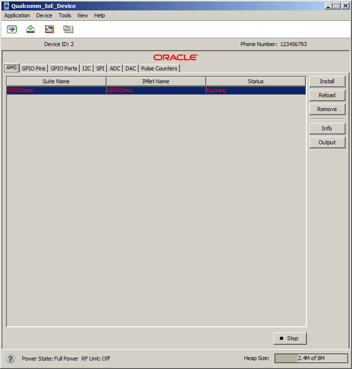
The Qualcomm_I0E_Device emulator is based on MEEP, but for a specific embedded platform, the Qualcomm Orion IoE device. Many of the menus and settings are the same as in the MEEP emulator.
The Qualcomm_IoE_Device emulator is launched from the Windows command prompt:
Change to the bin directory of the Oracle Java ME SDK 8 EA 2 distribution:
C:\>cd Java_ME_platform_SDK_8.0_EA\bin
To start the Qualcomm_IoE_Device emulator without a running application, enter:
C:\>emulator.exe -Xdevice:Qualcomm_IoE_Device -Xjam
To start the Qualcomm_IoE_Device emulator with a running sample application, enter the following command, using the generic command line shown here:
emulator.exe -Xdevice:Qualcomm_IoE_Device -Xdescriptor:location_of_jad_file
For example, to start the GPIODemo sample application, enter the following:
emulator.exe -Xdevice:Qualcomm_IoE_Device -Xdescriptor:C:\Java_ME_platform_SDK_8.0_EA\apps\GPIODemo\GPIODemo.jad
This launches the Qualcomm_IoE_Device emulator, as shown in Figure 3-26.
Figure 3-26 The Qualcomm_IoE_Device Emulator
